Cover closer

Inactive Publication Date: 2010-04-22
SHIMONISHI GIKEN KOGYO KK
View PDF13 Cites 5 Cited by
  • Summary
  • Abstract
  • Description
  • Claims
  • Application Information

AI Technical Summary

Benefits of technology

[0020]As a result, in accordance with the present invention, by making use of planetary gears in multiple stages, it is possible to achieve downsizing and a high reduction ra

Problems solved by technology

However, the driving mechanism is installed in the main body of the copying machine such that the design of the main body is subject to substantial constraints.
Also, in the case where the operator is a physica

Method used


Image

  • Cover closer
  • Cover closer
  • Cover closer

Examples


Embodiment Construction

[0036]Next, a cover closer in accordance with the present invention will be explained with reference to the accompanying drawings.

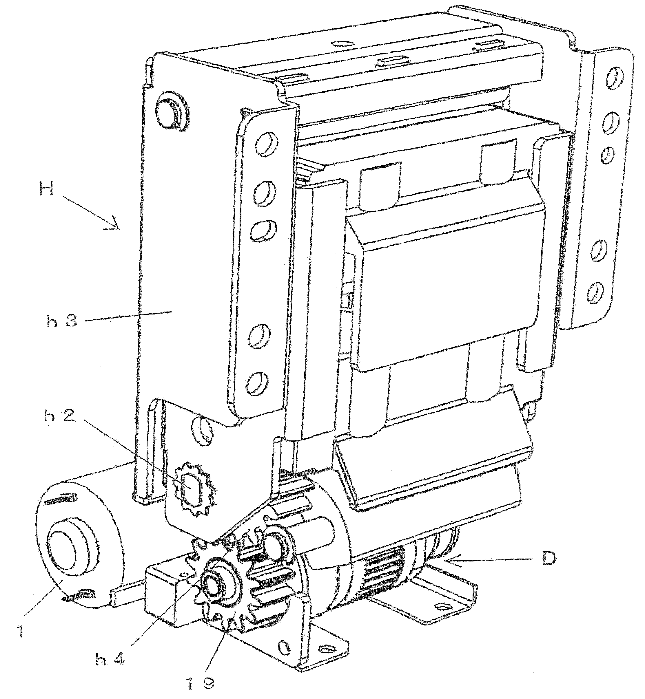
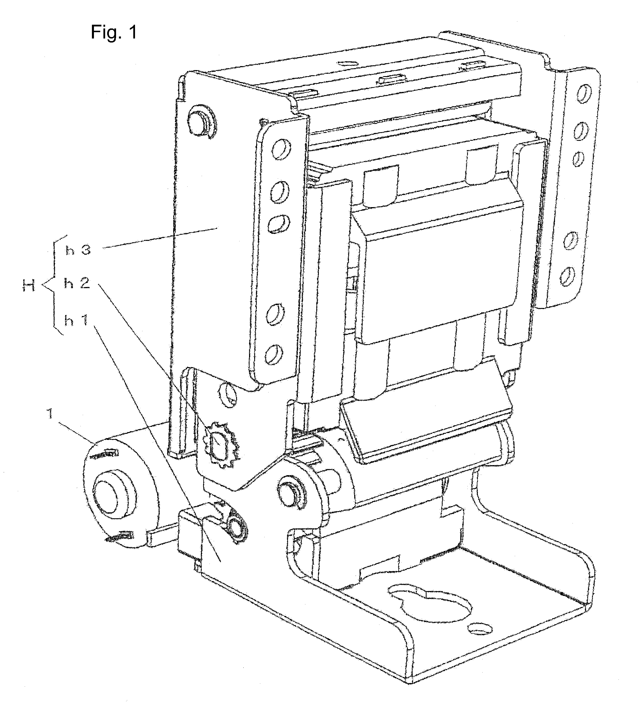
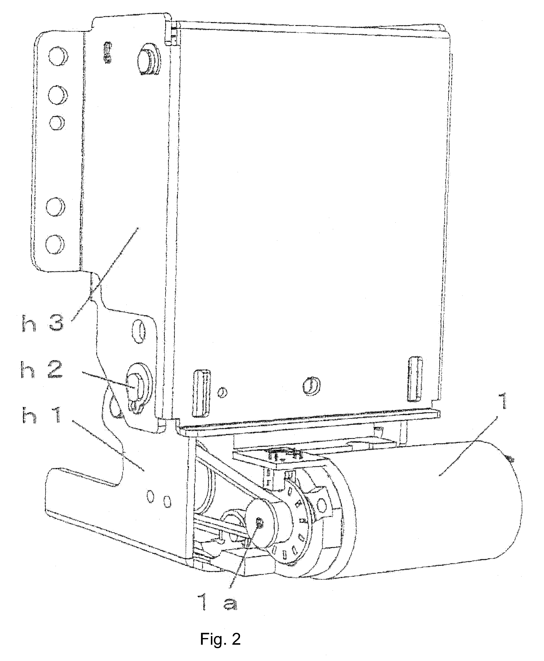
[0037]FIG. 1 through FIG. 3 show a cover closer in accordance with an embodiment of the present invention as a hinge mechanism for the original cover of a copying machine and so forth. In the figure, reference H denotes the joint structure of the cover closer, and reference D denotes a drive unit for driving the joint structure.

[0038]The joint structure H includes a stationary member h1, and a pivotal member h3 which is pivotally connect to the stationary member h1 through a hinge pin h2. The stationary member h1 is to be fixed to the main body of a copying machine or the like (not shown in the figure). The pivotal member h3 is to be fixed to the cover of the copying machine or the like.

[0039]FIG. 4 is a perspective view for generally showing the drive unit D which is composed mainly of an electric motor unit d1 and a reduction gear mechanism d2.

[0040]The...


PUM


Abstract

A cover closer having a drive unit for electrically opening and closing a cover of a copying machine or the like is described. The cover closer can ease the burden of manipulation of the cover and minimize the constraints on designing the main body of the copying machine and the like. The cover closer is provided with a compact drive unit having a high reduction ratio by the use of planetary gears which reduce the input torque necessary for opening and closing the cover, so as to downsize an electric motor used in the drive unit. The drive unit can therefore be installed within the hinge structure of the cover closer.

Description

BACKGROUND OF THE INVENTION[0001]1. Technical Field[0002]The present invention relates to a cover closer for use in a copying machine, office automation equipment and the like apparatus having an opening mechanism.[0003]2. Description of the Background Art[0004]At the present time, most copying machines are provided with covers which must be manually opened and closed. Some copying machines are equipped with motor-operated covers. However, the driving mechanism is installed in the main body of the copying machine such that the design of the main body is subject to substantial constraints.[0005]Also, in the case where the operator is a physically impaired person, it is a heavy burden to open and close the cover closer of a copying machine serving also as part of an automatic document feeder or any other heavy object, so that a solution is required.SUMMARY OF THE INVENTION[0006]Taking into consideration the above circumstances, it is an object of the present invention to provide a cov...

Claims


Application Information

Patent Timeline
IPC IPC(8): H05K5/03
CPCG03G15/16G03G21/1647G03G21/1633G03G2221/1687F16H1/32
Inventor SAITOU, KAZUOSUNAGA, YOSHIO
Owner SHIMONISHI GIKEN KOGYO KK
Why Eureka
Try Eureka