
Control Apparatus and Control Method for Automatic Transmission

a control apparatus and automatic transmission technology, applied in mechanical devices, transportation and packaging, gearing, etc., can solve the problems of large load applied to the specific rotary member, power performance deterioration, and inability to balance with the actual driving torqu

Active Publication Date: 2017-04-20
TOYOTA JIDOSHA KK
View PDF3 Cites 1 Cited by
  • Summary
  • Abstract
  • Description
  • Claims
  • Application Information

AI Technical Summary

Benefits of technology

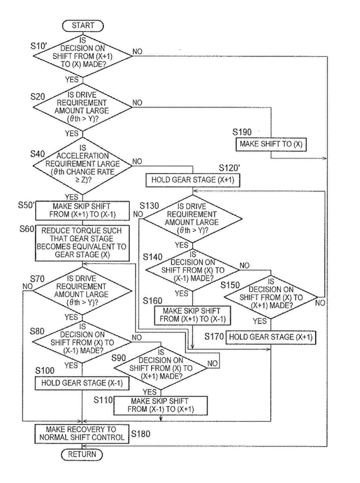
The patent text describes a control apparatus and method for an automatic transmission that reduces the load on specific components and minimizes the feeling of strangeness caused by driving torque. This is achieved by preventing the formation of gear stages that apply too much load on the transmission, and by reducing the input torque during gear shifts to prevent discomfort for the driver. Overall, the technology results in a more efficient and comfortable transmission experience.

Problems solved by technology

Therefore, the load applied to the specific rotary member becomes large in some cases.
However, when the input torque is limited, a required driving torque cannot be satisfied, and the power performance may deteriorate.
However, in this case, the specific gear stage is not formed, so a driving torque that ought to be obtained through the shift is not balanced with an actual driving torque.
As a result, a driver may develop a feeling of strangeness.

Method used


Image

  • Control Apparatus and Control Method for Automatic Transmission
  • Control Apparatus and Control Method for Automatic Transmission
  • Control Apparatus and Control Method for Automatic Transmission

Examples


Embodiment Construction

[0032]The embodiment of the disclosure will be described hereinafter in detail with reference to the drawings.

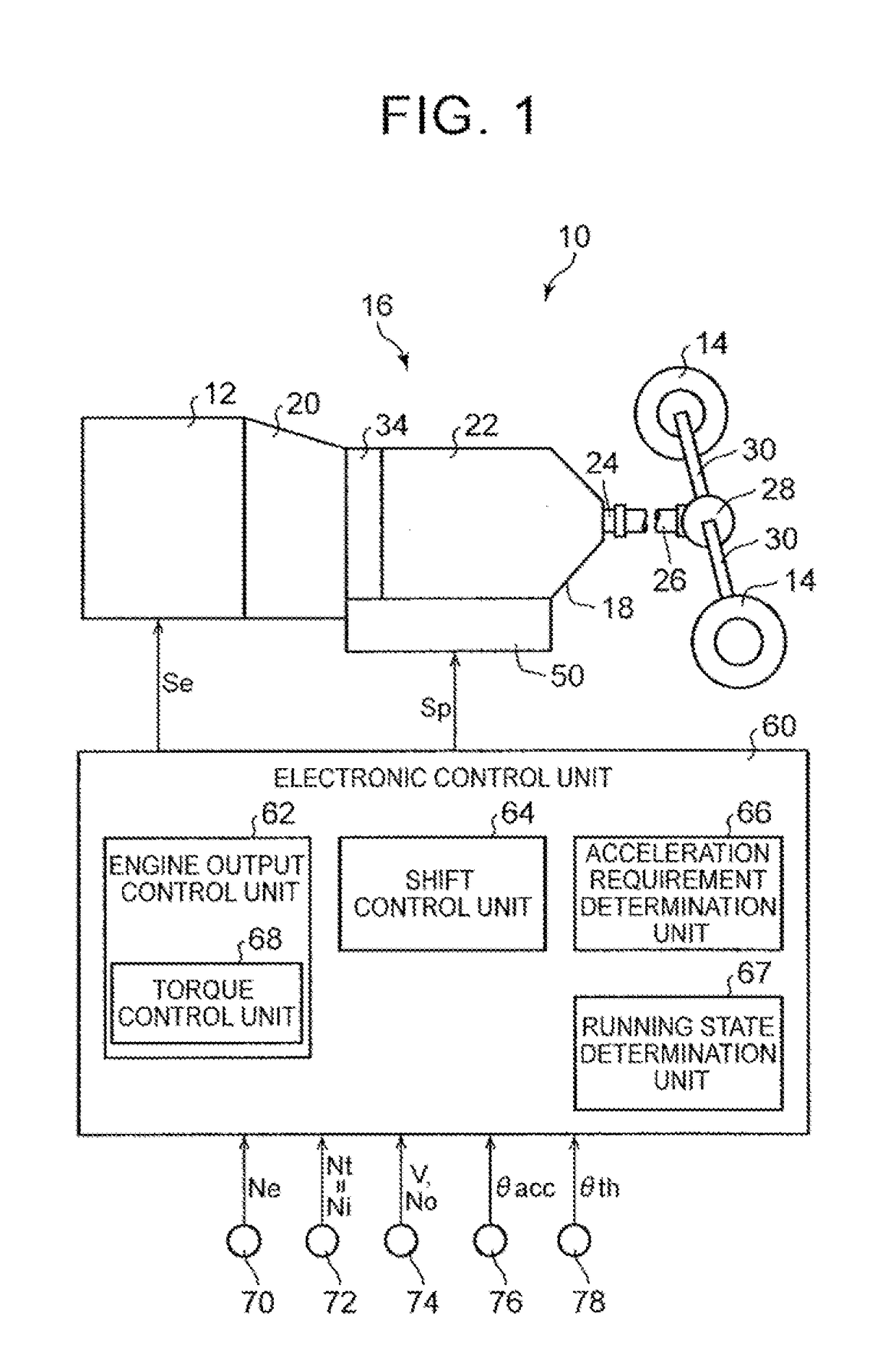
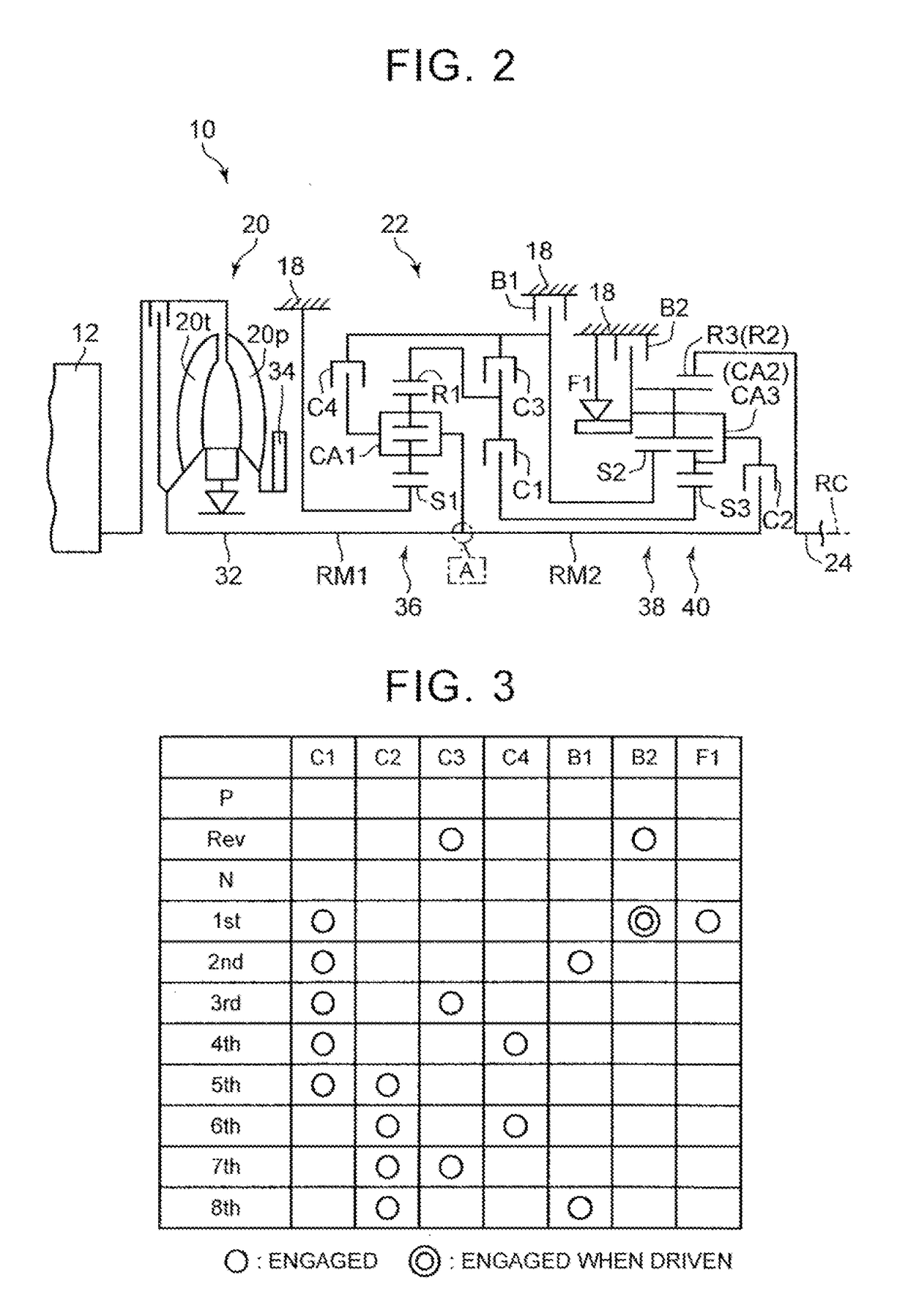
[0033]FIG. 1 is a view illustrating the general configuration of a vehicle 10 to which the disclosure is applied, and illustrating the essential part of a control system for various kinds of control in the vehicle 10. In FIG. 1, the vehicle 10 is equipped with an engine 12, driving wheels 14, and a power transmission device 16 that is provided in a power transmission path between the engine 12 and the driving, wheels 14. The power transmission device 16 is equipped with a torque converter 20 and an automatic transmission 22 that are disposed in a ease 18 as a non-rotary member that is attached to a vehicle body, a propeller shaft 26 that is coupled to a transmission output shaft 24 as an output rotary member of the automatic transmission 22, a differential gear mechanism (a differential gear) 28 that is coupled to the propeller shaft 26, a pair of axles 30 that are coupled t...


PUM


Abstract

When throttle valve opening degree is larger than predetermined throttle valve opening degree Y in the case where a decision on shift to gear stage at which maximum load is applied to predetermined rotary member of automatic transmission is made, the gear stage is not formed. Therefore, large load is restrained from being applied to the predetermined rotary member of the automatic transmission. Besides, gear stage that is lower in vehicle speed than the gear stage by one stage or gear stage that is higher in vehicle speed than the gear stage by one stage is formed depending on whether acceleration requirement is large or small. Therefore, driving torque corresponding to the acceleration requirement is likely to be obtained. In consequence, the load applied to the predetermined rotary member of the automatic transmission can be reduced, and feeling of strangeness can be restrained from being caused by the driving torque.

Description

INCORPORATION BY REFERENCE[0001]The disclosure of Japanese Patent Application No. 2015-204053 tiled on Oct. 15, 2015 including the specification, drawings and abstract is incorporated herein by reference in its entirety.BACKGROUND[0002]1. Technical Field[0003]The disclosure relates to a control apparatus and a control method for an automate transmission in which a plurality of gear stages having different gear ratios are selectively formed.[0004]2. Description of Related Art[0005]A control apparatus for an automatic transmission in which a plurality of gear stages having different gear ratios are selectively formed is well known. For example, a shift control apparatus described in Japanese Patent Application Publication No. 2010-112434 (JP 2010-112434 A) is such an example. in this Japanese Patent Application Publication No. 2010-112434 (JP 2010-112434 A), it is described that either first shift control for making shifts by stages or second shift control for making a shift skipping ...

Claims


Application Information

Patent Timeline
Patent Type & Authority Applications(United States)
IPC IPC(8): F16H61/02F16H59/44
CPCF16H61/0204F16H59/44F16H3/663F16H2200/2023F16H2200/2082F16H2200/006F16H2200/2046F16H2200/2066F16H2200/2007F16H61/04F16H2061/0459F16H3/666B60Y2300/184F16H61/0213F16H2061/0234
Inventor NATSUME, HIROSHI
Owner TOYOTA JIDOSHA KK
Learn More