
Compressed air energy storage compressor system and control method thereof

A compressed air energy storage and compressor technology, which is applied in pump control, mechanical equipment, machines/engines, etc., can solve the problems of reduced energy storage capacity of compressed air, energy loss of high-pressure compressed air, and increased air temperature of air storage tanks. Achieve power reduction, improve conversion efficiency, and reduce energy loss

Pending Publication Date: 2019-03-08
GUIZHOU POWER GRID CO LTD
View PDF8 Cites 1 Cited by
  • Summary
  • Abstract
  • Description
  • Claims
  • Application Information

AI Technical Summary

Problems solved by technology

[0005] The technical problem to be solved by the present invention is to provide a compressed air energy storage compressor system and its control method to solve the problem of the pressure in the air storage tank of the prior art multi-stage compressor compressed air energy storage power station. Low, when the high-pressure compressed air enters the air storage tank, due to the large pressure difference, the high-pressure compressed air expands and does work, which makes the air temperature in the air storage tank rise, resulting in the problem of decreased energy storage capacity of compressed air and energy loss of high-pressure compressed air question

Method used


Image

  • Compressed air energy storage compressor system and control method thereof
  • Compressed air energy storage compressor system and control method thereof
  • Compressed air energy storage compressor system and control method thereof

Examples


Embodiment Construction

[0024] Further illustrate the present invention below in conjunction with accompanying drawing, should be understood that this example is only used to illustrate the present invention and is not intended to limit the scope of the present invention, after having read the present invention, those skilled in the art all can modify various equivalent forms of the present invention fall within the scope defined by the appended claims of this application.

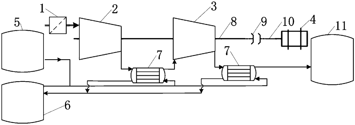
[0025] A compressed air energy storage compressor system, comprising: an air inlet filter 1, at least one low-pressure stage compressor 2, at least one high-pressure stage compressor 3, an electric motor 4, a cold storage tank 5, a heat storage tank 6, at least two Heater 7, compressor transmission shaft 8, hydraulic coupler 9, motor transmission shaft 10, gas storage tank 11 and related pipeline valves, the outlet of the air inlet filter 1 is connected to the inlet of the low-pressure stage compressor 2, and the The outlet of th...


PUM


Abstract

The invention discloses a compressed air energy storage compressor system and a control method thereof. A hydraulic coupler is connected into the compressed air energy storage compressor system, and amotor is connected with the hydraulic coupler through a motor drive shaft, and the hydraulic coupler is connected with a high-pressure stage compressor through a compressor drive shaft; through the speed adjusting function of the hydraulic coupler, the rotating speed of the compressor can be reduced, and the pressure ratio of the compressor can be adjusted, the pressure of compressed air of compressor outlets can be changed before the compressed air pressure in an air storage tank does not reach the rated pressure, so that the outlet pressure of the compressors is matched with the pressure ofthe air storage tank, and the energy loss of the high pressure compressed air is reduced; and meanwhile, the input torque of the compressors is reduced due to the adjustment of the hydraulic coupler,the motor power is reduced, and the aims that the compressed air energy storage system reduces energy loss and improves electric-electric conversion efficiency are achieved.

Description

technical field [0001] The invention relates to the field of multi-stage compressor systems, in particular to a compressed air energy storage compressor system and a control method thereof. Background technique [0002] Compressed air energy storage has the advantages of large energy storage scale, long storage period, and less environmental pollution. It is considered to be one of the most promising large-scale power energy storage technologies. [0003] Compressors play an important role in compressed air energy storage and are the main equipment for converting electrical energy into air internal energy. Reducing compressor output while meeting system operating requirements is of great significance for system energy saving and improving electrical-electrical efficiency. At present, the operation mode of the multi-stage compressor is that regardless of the pressure of the gas storage tank, all the compressors are put into operation, the outlet pressure is high and the press...

Claims


Application Information

Patent Timeline
Patent Type & Authority Applications(China)
IPC IPC(8): F04B41/02F04B41/06F04B35/04F04B49/08F04B49/20
CPCF04B35/008F04B35/04F04B41/02F04B41/06F04B49/08F04B49/20Y02E60/16
Inventor 张世海文贤馗邓彤天钟晶亮马新惠李盼陈雯吴宓王锁斌
Owner GUIZHOU POWER GRID CO LTD
Learn More