Multi-Hybrid Aircraft Engine

a hybrid aircraft engine technology, applied in the field of hybrid aircraft engines, can solve the problems of difficult to fly hundreds of passengers at a time, electrical powered planes are generally slow, and electric planes tend to be slow, so as to achieve torque and speed, prolong battery life, and increase fuel efficiency

Inactive Publication Date: 2019-06-20
ROBERT A BINGHAM
View PDF0 Cites 2 Cited by
  • Summary
  • Abstract
  • Description
  • Claims
  • Application Information

AI Technical Summary

Benefits of technology

[0012]The utility of the multi-hybrid aircraft engine may be based, at least in part, on the size differences of the compressor pistons, the drive block pistons, and the driven block pistons. In some embodiments, the drive block pistons are larger (e.g., wider in diameter) than the compressor pistons, which are larger than the driven block pistons. Because the compressor pistons are smaller than the drive block pistons, the input torque required to drive the primary compressor may be relatively low. Further, due to the relatively large size of the drive block pistons relative to the driven block pistons, the drive block may produce a relatively large drive force relative to the drive force of the driven block. The differences in size between the compressor pistons, the drive block pistons, and the driven block pistons may provide advantages resulting from the application of Pascal's principle. These advantages and the configuration of the multi-hybrid aircraft engine make it possible for a single primary compressor to drive one or more multipliers with very little input torque and speeds. Moreover, the size differences between the compressor pistons, the driven block pistons, the drive block pistons, and the configuration may depend on design requirements.
[0015]The rotating driven block may drive one or more driven block pistons that are designed to translate within chambers of the driven block as they are carried around on piston tracks of the swash plate. The translating pistons draw compressible fluid from inlet passages of the valves into the driven block, compress the compressible fluid and discharge it to the speed regulator. The compressed air from the driven block merges with the compressed air from the primary compressor, thereby, increasing the flow of compressed air through the drive block. The increased flow of compressed air through the drive block further increases the rotational energy of the drive block over time.
[0017]The compressed air from the compressed air tank may be allowed to flow through the speed regulator and then to the drive block to drive the drive block pistons so that the motion of the drive block pistons causes the drive block to be rotated. The rotational energy of the drive block may be transferred to the driven block via the primary shafts connected to the drive block and driven block to allow the driven block to drive the driven block pistons. The driven block pistons are coupled to the swash plate configured to convert the rotational motion of the driven block pistons to translational motion, thus, permitting the driven block pistons to slide in and out of chambers within the driven block.
[0018]The multiplier further comprises a set of insertable seals and valves with inlet and outlet passages for receiving and ejecting compressible fluid. The set of insertable seals are designed to permit the flow of both compressible and non-compressible fluid through desired passages of the valves and the driven block / drive block and also for preventing the mixing of compressible fluid with non-compressible fluid.
[0022]The output shafts driven by the drive block drives the driven block to provide the drive block an increase of speed as compressed air from the driven block merges with the compressed air from the primary compressor. The increased rotational speed of the drive block results in an increased rotational speed of the output shafts that drive the front fan and the axial compressor.
[0024]The advantages of multi-hybrid aircraft engines and multi-hybrid turbojet engines include a higher fuel efficiency and extended battery life that results from configurations that provide torques and speeds multiplications. In other words, conversely to conventional configurations that include a drive system in which an electric motor and / or an internal combustion engine is / are coupled directly to the propeller, the present disclosure provides a drive system in which the electric motor and / or the internal combustion engine drive a compressor (primary compressor) that compresses air to another unit of the engine so that torque and speeds are multiplied creating more thrust than known hybrid aircraft engines. In addition, a multi-hybrid aircraft engines / multi-hybrid turbojet engines can efficiently run on compressed air.

Problems solved by technology

Most conventional hybrid aircraft engines, particularly, those powered by electric motors that are driven by one or more batteries that are charged by an internal combustion engine, involve far less thrust, which is the reason electric planes tend to be slow.
Electrical powered planes are generally slow, which is why it is challenging to fly hundreds of passengers at a time.
One of the biggest challenges of electrical powered planes is battery technology, specifically a battery's specific energy, or the limited amount of energy it can store for a given amount of weight.
This limitation greatly poses challenging complications in the use of one or more electric motors for powering a plane.

Method used


Image

  • Multi-Hybrid Aircraft Engine
  • Multi-Hybrid Aircraft Engine
  • Multi-Hybrid Aircraft Engine

Examples


Embodiment Construction

[0076]The multi-hybrid aircraft engine above is described in further detail below in connection with exemplary embodiments of the invention depicted in the accompanying drawings.

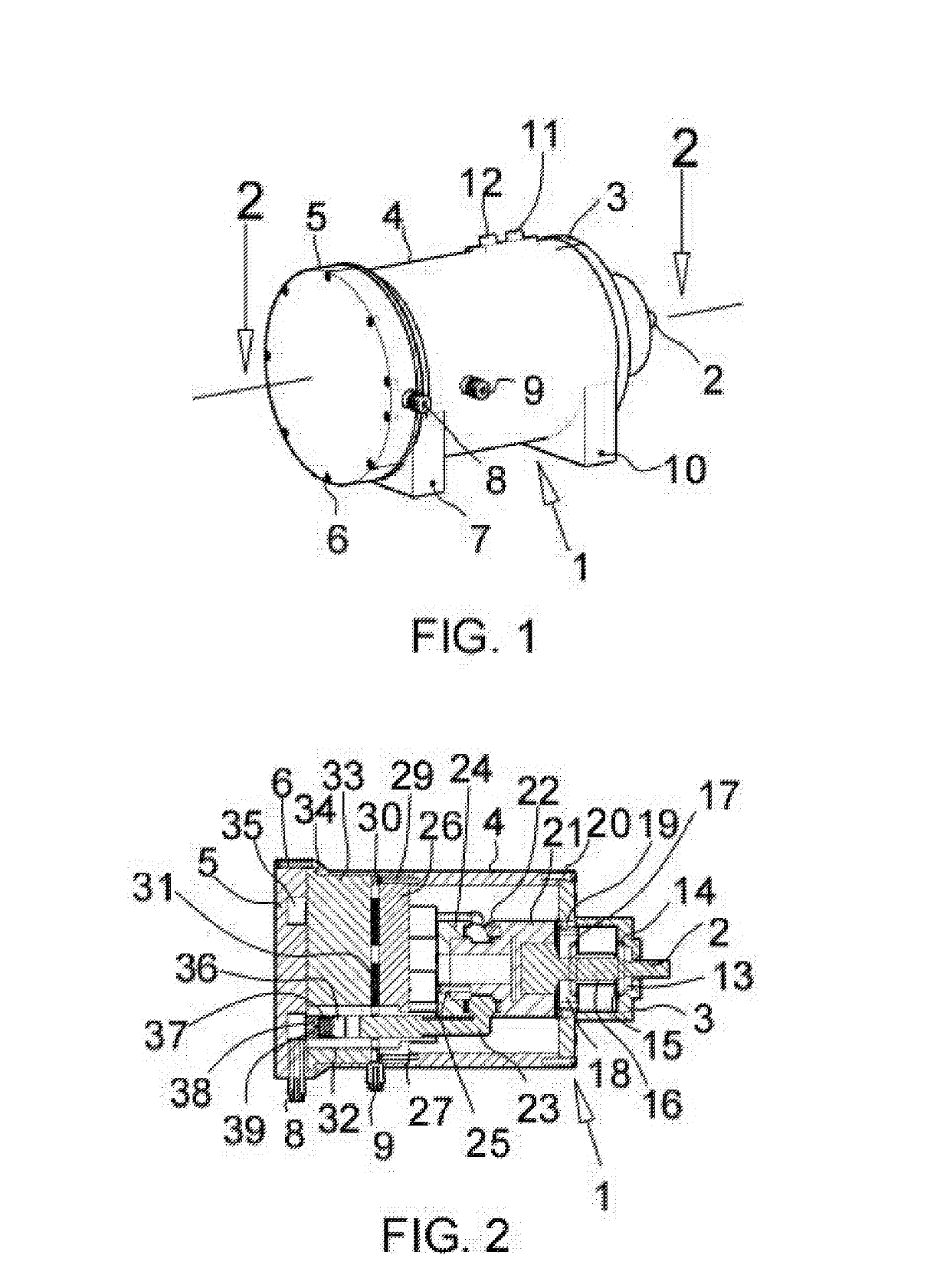
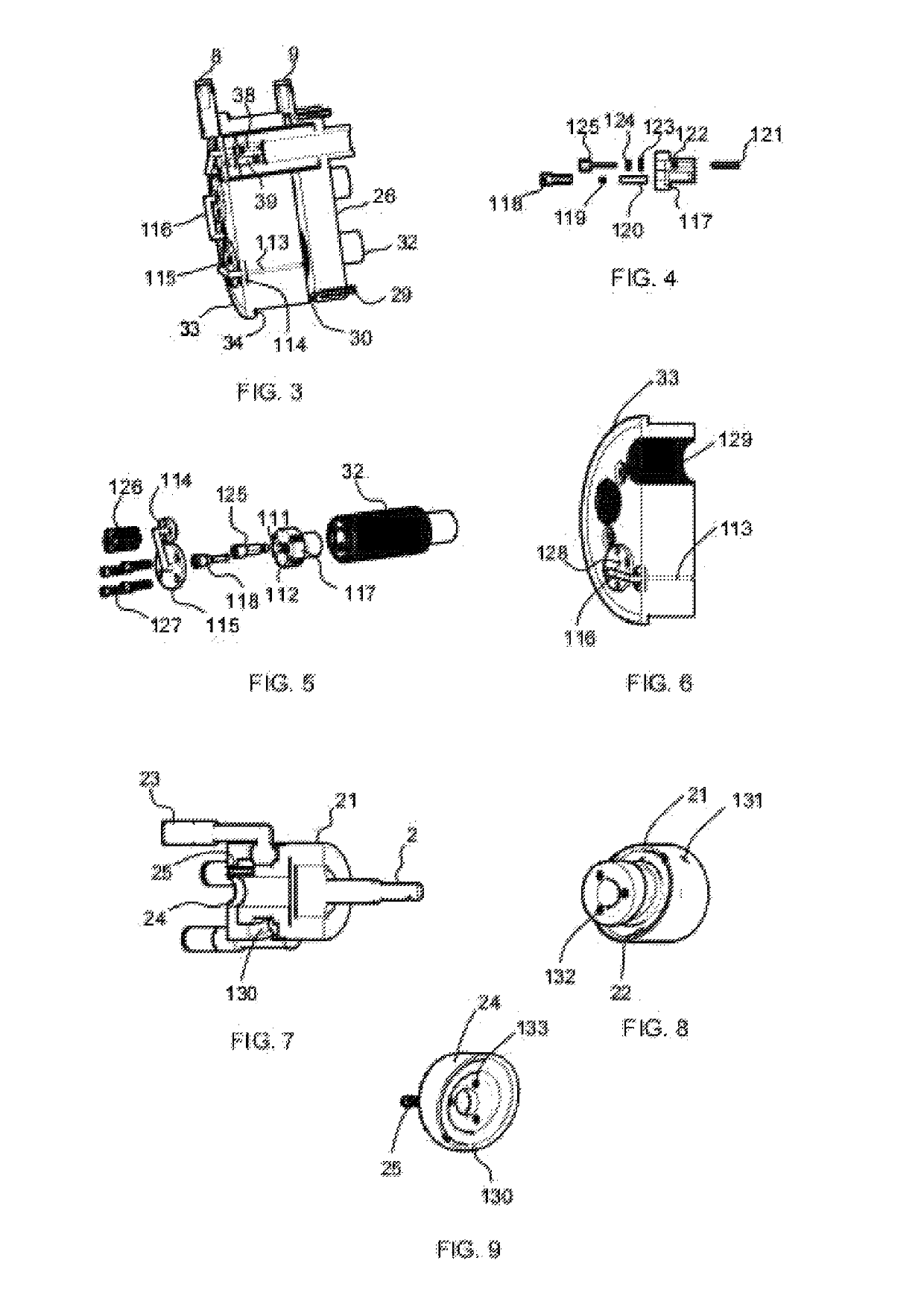
[0077]The primary compressor 1 as shown in FIGS. 1-9 has a power shaft 2 extending though a bearing support 18, a tapered roller bearing 14 and 17, a hallow rod 16, and a snap ring 15. The power shaft 2 may also go through an oil seal 13 seated in a front covering 3 that is coupled to a compressor housing 4 with bolts 20. The bearing support 18 may be connected to the front covering 3 and held together with bolts 19. The hallow rod 16 ensures that the tapered roller bearings 14 and 17 maintain their positions and the snap ring 15 may prevent the power shaft 2 from moving back and forth. The power shaft 2 may be coupled to a swash plate 21 with bolt 131 as shown in FIG. 8. The swash plate 21 has tracks 22 and 130, see FIG. 7, for mounting compressor pistons 23, and a swash plate retainer 24 coupled to swash p...


PUM


Abstract

A multi-hybrid aircraft engine that includes a primary compressor 1, a multiplier 199 comprising a drive block, a driven block, driven block pistons 54, and primary shafts 78 and 41; an output shaft 105, and a speed regulator 167. The multi-hybrid aircraft engine is configured such that the primary compressor 1 is fluidly connected to the drive block 46 which is mechanically connected to the driven block 57. The primary compressor 1 pumps compressible fluid to the drive block 46 through the speed regulator 167 to drive the drive block 46, which in turn, drives the primary shafts 78 and 41. The primary shafts 78 and 41 drive the driven block 57, which pumps fluid via the driven block pistons 54, to the drive block 46 through the speed regulator 167 to increase the flow rate of compressible fluid within the multi-hybrid aircraft engine. Furthermore, the driven block 57 provides a shaft 68 that is connected to sets of planetary gears 62 connected to an output shaft 105 that drives a propeller 186.

Description

RELATED APPLICATIONS[0001]This application claims the benefit of U.S. Provisional Application No. 62 / 380,703 filed Aug. 29, 2016, which is herein incorporated by reference.TECHNICAL FIELD[0002]The present disclosure relates generally to the field of aircraft engines and, in particular, to a hybrid aircraft engines powered by an external power source such as combustion engine, an electric motor, a compressed air, and / or man power.BACKGROUND OF THE INVENTION[0003]The disclosure set forth herein relates to an arrangement comprising a speed regulator, a primary compressor and a multiplier comprising a rotatable drive block, a rotatable driven block, a swash plate, and driven block pistons in which; the primary compressor, when driven by an external power source compresses air to the multiplier through the speed regulator. The compressed air when allowed to flow through the multiplier drives the rotatable drive block that is mechanically connected to the rotatable driven block configured...

Claims


Application Information

Patent Timeline
Patent Type & Authority Applications(United States)
IPC IPC(8): F02K5/00B64D27/24B64D27/16
CPCF02K5/00B64D27/24B64D27/16F02C7/36F02K3/06B64D2027/026F05D2260/4031Y02T50/60B64U50/00
Inventor AZUNDAH, ORLORUNFEMI JACOB
Owner ROBERT A BINGHAM
Why Eureka
Try Eureka