
Light emitting diode-based lamp having a volume scattering element

a light-emitting diode and light-emitting diode technology, which is applied in the direction of semiconductor devices for light sources, fixed installations, lighting and heating apparatus, etc., can solve the problems of affecting the performance of the light-emitting element b, cosmetically unappealing, and relatively tight alignment toleran

Inactive Publication Date: 2010-04-22
OSRAM SYLVANIA INC
View PDF16 Cites 52 Cited by
  • Summary
  • Abstract
  • Description
  • Claims
  • Application Information

AI Technical Summary

Problems solved by technology

However, there are several drawbacks to this lamp.
The primary drawback is that the lamp itself is cosmetically unappealing.
First, the element 600 has an optical axis, and requires fairly careful alignment to operate properly. If the LEDs are misaligned slightly away from their target positions, the light pattern within the element 600 shifts dramatically, with some exiting angles receiving more light and some exiting angles receiving less.
Second, because element 600 operates in a deterministic manner and relies on a generally smooth surface for its optimal operation, element 600 is especially vulnerable to defects. Specifically, surface defects, such as scratches, structure defects, such as size or shape errors, and material defects, such as refractive index variations or contamination, can seriously degrade the performance of the element 600.
However, it still has the drawback that the deterministic propagation within the lens 270 creates a fairly tight alignment tolerance between the LEDs and the lens 270.
This variation in brightness would be visible from a variety of angles, because of the glass frosting, but the surface diffuser would not mask the variations in brightness on the frosted bulb surface.

Method used


Image

  • Light emitting diode-based lamp having a volume scattering element
  • Light emitting diode-based lamp having a volume scattering element
  • Light emitting diode-based lamp having a volume scattering element

Examples


Embodiment Construction

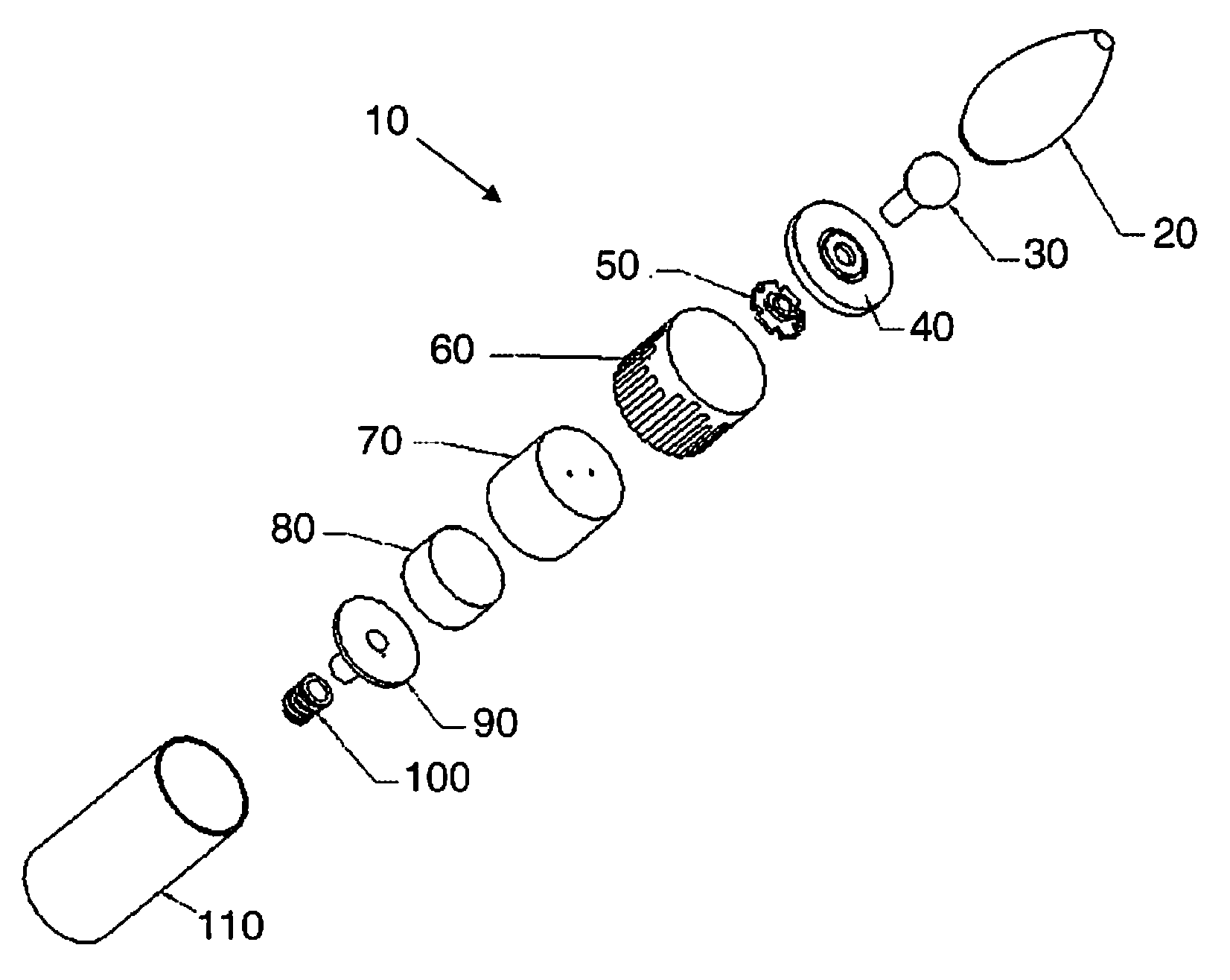
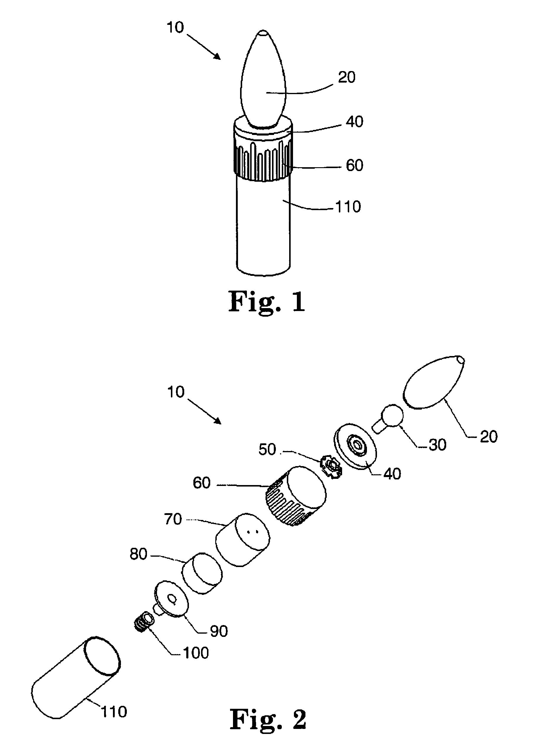
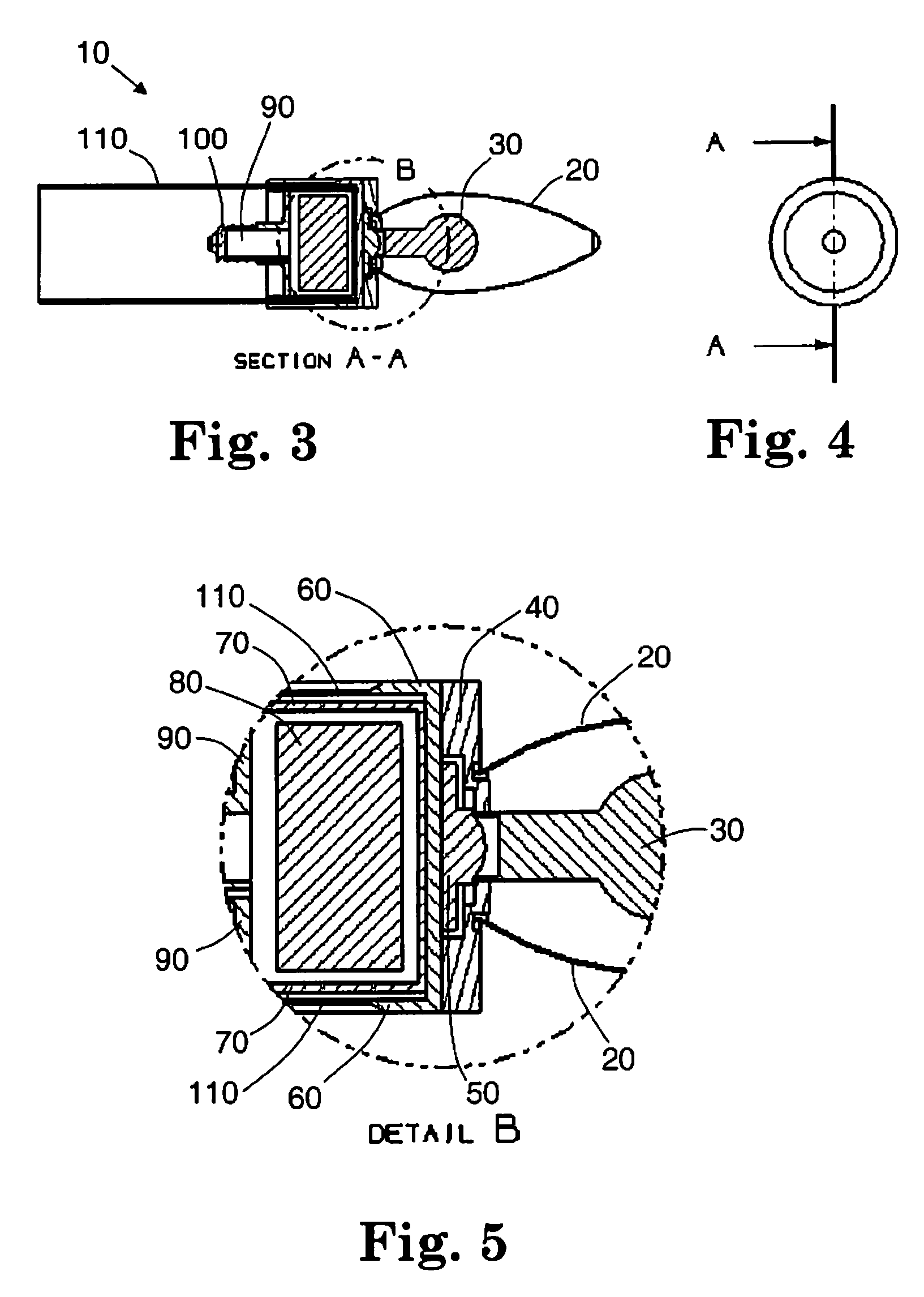
[0050]A lamp having a candle-like appearance and using one or more light-emitting diodes (LEDs) as its light source is presented. The candle-like appearance arises because light is emitted from only a small volume at or near the center of the bulb. The heat sink and control electronics are located outside the bulb of the lamp. Inside the bulb is a set of secondary optics that guide the light from one or more LEDs to an emission point at a prescribed location in the interior of the bulb. The secondary optics include a light pipe that guides light away from the LED chip, and a volume scattering element that receives the light from the light pipe and scatters it into various directions. The volume scattering element is made from a transparent base material, and includes transparent particles of a predetermined size and refractive index. Because the lamp is typically used in an overhead position, such as in a hanging chandelier, the density of particles in the volume scattering element,...


PUM


Abstract

A lamp having a candle-like appearance and using one or more light-emitting diodes (LEDs) as its light source is presented. The candle-like appearance arises because light is emitted from only a small volume at or near the center of the bulb. The heat sink and control electronics are located outside the bulb of the lamp. Inside the bulb is a set of secondary optics that guide the light from one or more LEDs to an emission point at a prescribed location in the interior of the bulb. The secondary optics include a light pipe that guides light away from the LED chip, and a volume scattering element that receives the light from the light pipe and scatters it into various directions. The volume scattering element is made from a transparent base material, and includes transparent particles of a predetermined size and refractive index. Because the lamp is typically used in an overhead position, such as in a hanging chandelier, the density of particles in the volume scattering element, the particle size and the particle refractive index are chosen to produce a scattering pattern that directs more light downward (toward the base of the bulb) than upward, while maintaining a reasonable efficiency (fraction of produced light that successfully exits the lamp). Simulation results are presented.

Description

CROSS-REFERENCE TO RELATED APPLICATIONS[0001]The present application claims priority under 35 U.S.C §119(e) to provisional application No. 61 / 105,980, filed on Oct. 16, 2008 under the same title. Full Paris Convention priority is hereby expressly reserved.STATEMENT REGARDING FEDERALLY SPONSORED RESEARCH OR DEVELOPMENT[0002]Not ApplicableBACKGROUND OF THE INVENTION[0003]1. Field of the Invention[0004]The present invention is directed to a light emitting diode-based lamp having a volume scattering element inside the bulb.[0005]2. Description of the Related Art[0006]Prior to the invention of the light bulb, candles were a stylish choice for fancy lighting. A chandelier would hang from the ceiling of a room, and would support several candles, often arranged in an ornate and decorative manner around the circumference of the chandelier.[0007]When incandescent light bulbs became popular, many electric chandeliers emulated the look of the candle-holding chandeliers. Instead of a series of c...

Claims


Application Information

Patent Timeline
IPC IPC(8): F21V13/00F21V29/00
CPCF21K9/52F21K9/56F21S8/065F21V29/20F21W2121/00F21Y2101/02F21V3/02F21K9/61F21K9/64F21Y2115/10F21V29/74H01L33/54
Inventor HUANG, MICHELLELEE, JUNWONSPEHALSKI, TOMULLOA, FERNANDO
Owner OSRAM SYLVANIA INC
Learn More