Watch movement

a technology of movement and movement, applied in the direction of mechanical time indication, instruments, horology, etc., can solve the problem of difficult to achieve the distribution of components in this part of the watch, and achieve the effect of optimizing the operating conditions of the balan

Active Publication Date: 2010-04-22
COMPLITIME SA
View PDF8 Cites 4 Cited by
  • Summary
  • Abstract
  • Description
  • Claims
  • Application Information

AI Technical Summary

Benefits of technology

[0005]The primary aims of the present invention are to enable the realization of a movement occupying a limited vo

Problems solved by technology

The distribution of the components arranged in

Method used


Image

  • Watch movement
  • Watch movement
  • Watch movement

Examples


Embodiment Construction

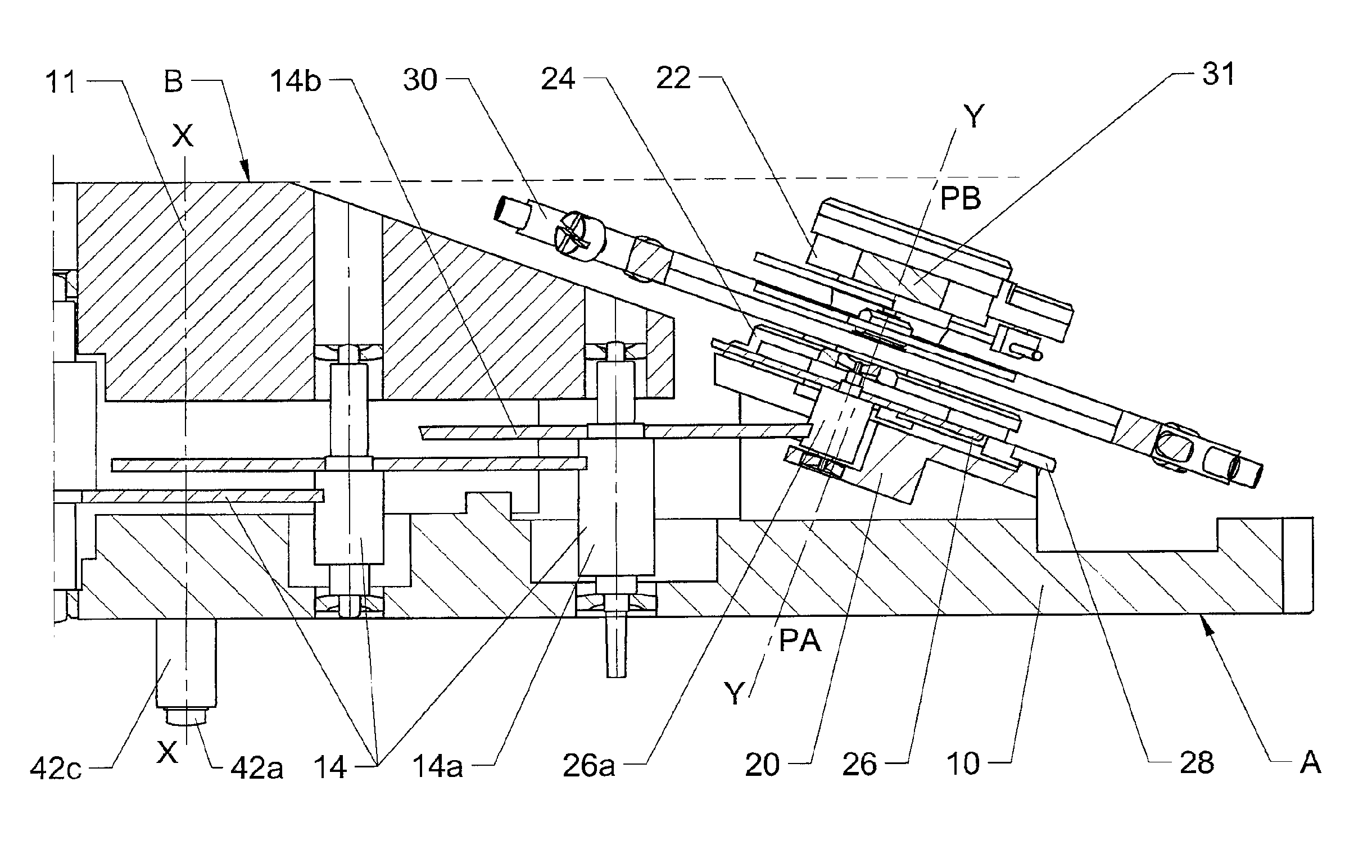
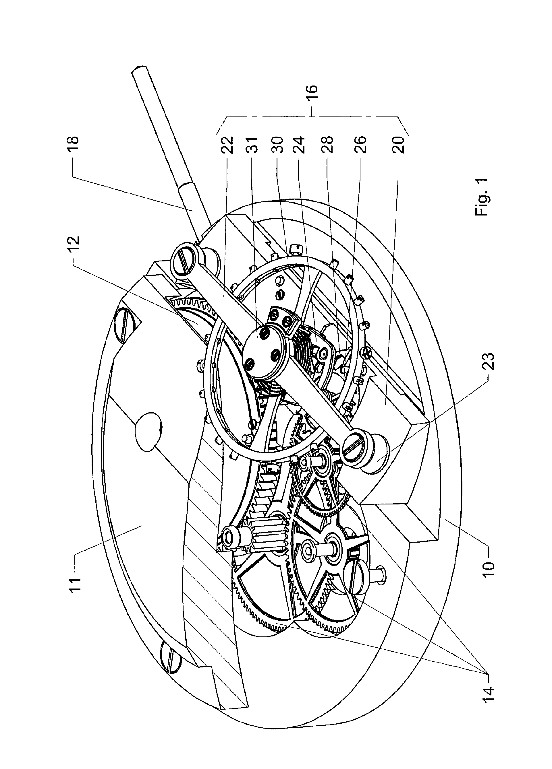
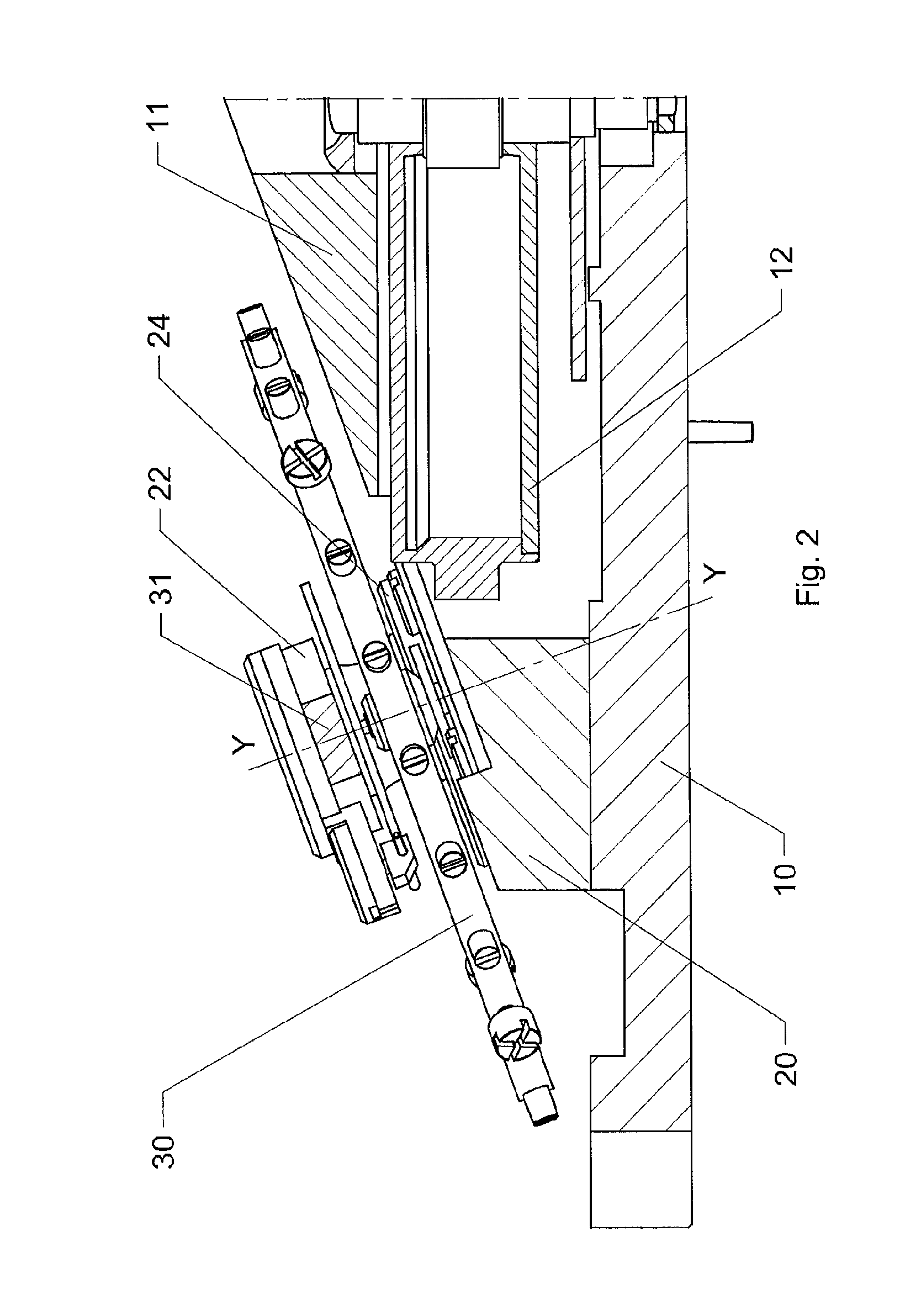
[0026]The watch movement illustrated in FIGS. 1 to 4 comprises in particular and traditionally a plate 10 and a plate bar 11, partially removed in FIG. 1 and secured on the plate 10 using screws (not referenced), a barrel 12 forming the energy source, a going train 14, a regulating organ made up of a platform escapement 16 and a winding and setting mechanism comprising in particular a setting stem 18, only component visible in these figures. The plate 10 is of a generally discoid shape and defines a central axis XX (FIG. 3). In this movement, the barrel 12 and the components of the going train 14 turn around axes parallel to the axis XX.

[0027]The platform escapement 16 comprises a base 20 and, secured on the latter using screws (not referenced), a balance-cock 22, two columns 23 inserted between the base 20 and the cock 22 (FIG. 1), and an escapement bridge 24. An escape wheel 26 and an anchor 28, together forming the escapement of the watch, are mounted pivoting between the base 20...


PUM


Abstract

A watch movement, includes a frame (10, 11, 20, 22, 24), defined by a first and a second parallel plane surface and defining reference planes (A, B), the second plane (B) being located alongside the movement for placing adjacent to the wrist of the wearer, at least one balance wheel (30), pivoting in bearings fixed in the frame, at least one escape mechanism (26, 28) providing support for the balance wheel, an energy source (12), clockwork finishing movements (14), connecting the energy source to the escape mechanism and motion work (42).The balance wheel turns about an axis (YY), inclined in relation to the reference planes and intersecting the same, the point of intersection (PA) of the axis (Y) with the first plane (A) being closer to the centre of the movement than the point of intersection (PB) of the axis (Y) with the second plane (B).

Description

TECHNICAL FIELD[0001]The present invention relates to watch movements, more particularly of the type comprising a sprung balance. Movements of this type comprise a frame. They are inserted between first and second parallel plane surfaces. The first surface generally serves as support for the dial, while the second is defined by the upper face of the bridges or of the oscillating weight, or the upper face of parts making up a mechanism. This face is generally intended to be adjacent to the wrist of the wearer.BACKGROUND OF THE INVENTION[0002]The frame supports wheel assemblies generally arranged such that their axes of rotation are parallel to each other and perpendicular to said plane surfaces. These wheel assemblies, of discoid shape, are more or less superimposed, depending on their position in reference to the frame. One of them, arranged to support time indicator organs, is arranged in the vicinity of the first surface.[0003]One also knows movements built in several sections, en...

Claims


Application Information

Patent Timeline
IPC IPC(8): G04B15/00G04B5/00
CPCG04B17/06G04B33/08G04B29/02G04B19/082
Inventor GREUBEL, ROBERTFORSEY, STEPHEN
Owner COMPLITIME SA
Why Eureka
Try Eureka