Method for transmitting and receiving feedback information

a communication system and feedback information technology, applied in the field of communication system feedback information, can solve problems such as the inability to improve the system, and achieve the effects of improving the system capability, increasing the cluster size, and reducing the amount of unnecessary feedback information

Active Publication Date: 2010-04-22
LG ELECTRONICS INC
View PDF9 Cites 33 Cited by
  • Summary
  • Abstract
  • Description
  • Claims
  • Application Information

AI Technical Summary

Benefits of technology

[0015]An object of the present invention devised to solve the problem lies on a method for transmitting and receiving feedback information, which is capable of efficiently reducing the amount of feedback information and improving system capability by determining and using a cluster size for computing feedback information such as a CQI and a PMI and a period for reporting the feedback information in consideration of downlink statuses of UEs.
[0022]Preferably, the determining and transmitting of the cluster size to the at least one UE may include increasing the cluster size to be transmitted to the UE as a coherence frequency received the UE is increased.
[0023]According to an embodiment of the present invention, since a cluster size as a unit for computing the feedback information and a reporting period of the feedback information are not uniformly determined by a base station, that is, are determined in consideration of downlink channel statuses of UEs, it is possible to reduce the amount of unnecessary feedback information and improve system capability. Preferably, since a cluster size for computing a CQI and a cluster size for computing a PMI have a multiple relationship, it is possible to prevent wrong feedback information from being transmitted.

Problems solved by technology

Therefore, if the base station determines a cluster size and reporting period, which are not suitable for the channel statuses of the UEs, in a state in which the base station does not know the statuses of the UEs, system capability may deteriorate.

Method used


Image

  • Method for transmitting and receiving feedback information
  • Method for transmitting and receiving feedback information
  • Method for transmitting and receiving feedback information

Examples


Embodiment Construction

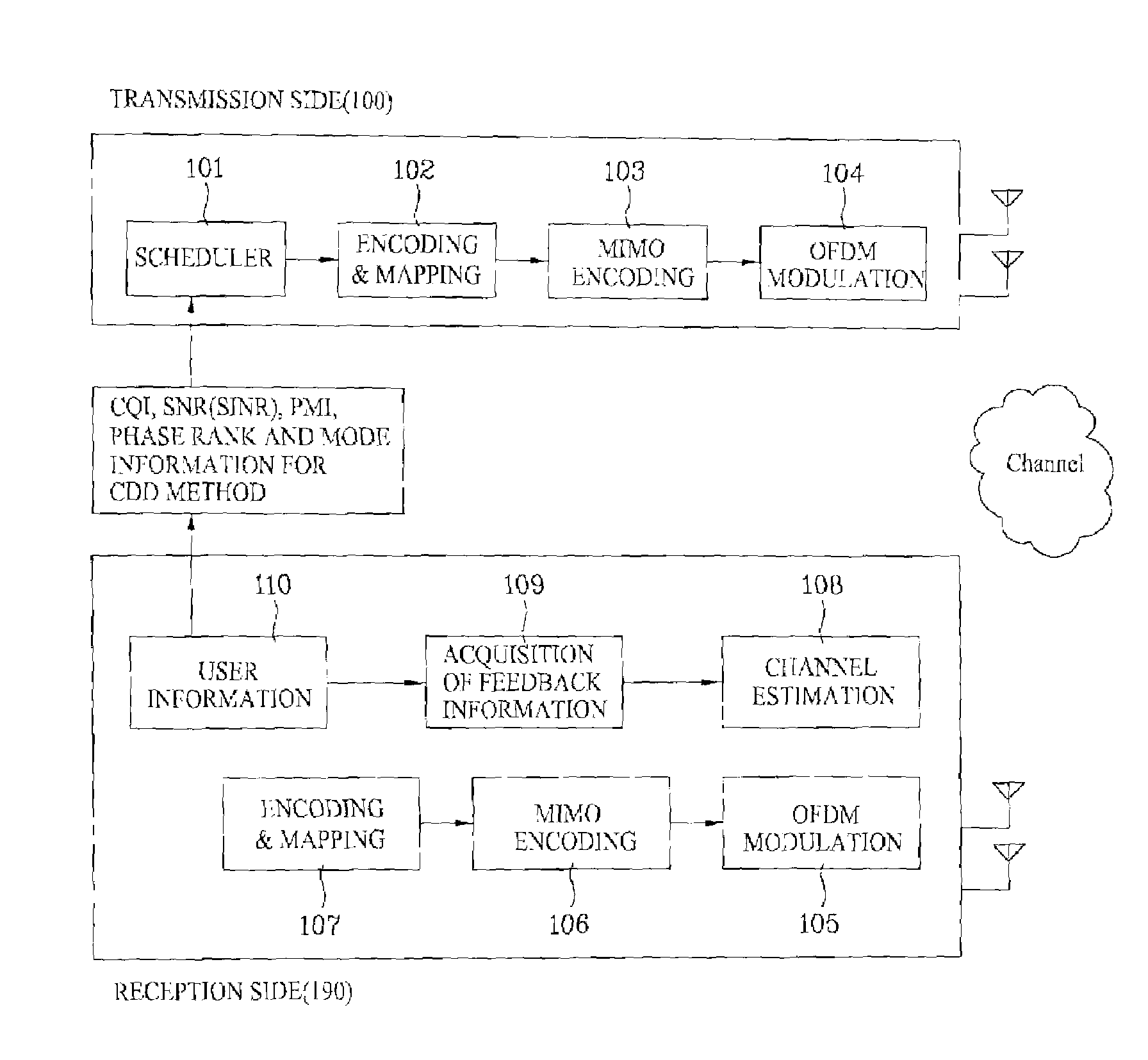
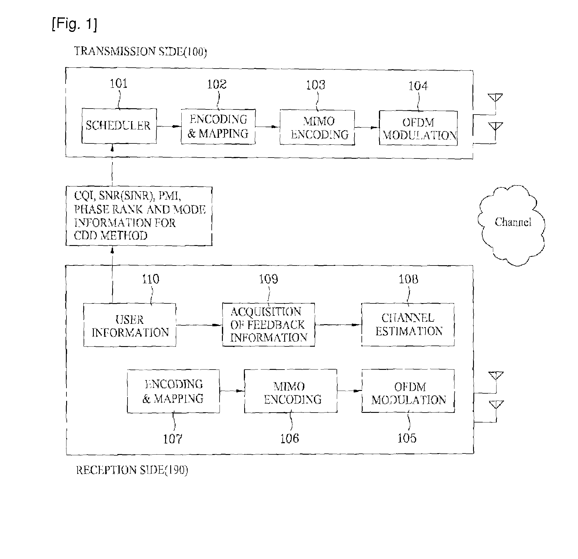
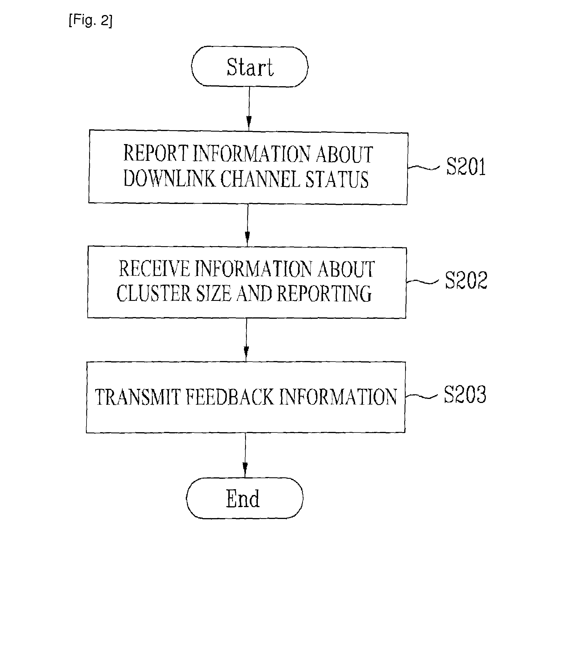
[0032]Hereinafter, preferred embodiments of the present invention will be described in detail with reference to the accompanying drawings. The present invention will become more fully understood from the detailed description provided herein below and the accompanying drawings which are given by way of illustration only, and thus do not limit the present invention.

[0033]The following detailed description includes details in order to provide complete understanding of the present invention. However, it will be apparent to those skilled in the art that the present invention can be embodied without the details. In some cases, known structures and devices are omitted in order to avoid ambiguity of the concept of the present invention or main functions of the structures and the devices are shown in a block diagram. The same reference numbers will be used throughout the drawings to refer to the same or like parts.

[0034]As described above, the present invention relates to a method for transm...


PUM


Abstract

A method for efficiently transmitting and receiving feedback information is disclosed. A cluster size as a unit for computing the feedback information and a reporting period of the feedback information are not uniformly determined by a base station. Information about a downlink channel status of each user equipment is reported, the cluster size and feedback period for computing and reporting the feedback information are determined using the information about the downlink channel status of each user equipment, and the feedback information is transmitted / received, thereby improving system capability.

Description

TECHNICAL FIELD[0001]The present invention relates to feedback information of a communication system, and more particularly to, a method for transmitting and receiving feedback information in consideration of a downlink channel status of a user equipment.BACKGROUND ART[0002]In a communication system, a reception side transmits feedback information of a signal received from a transmission side so as to accomplish efficient communication. The transmitted feedback information will now be briefly described in, for example, a multiple input-multiple output (MIMO) communication.[0003]FIG. 1 is a schematic diagram showing the configurations of transmission and reception sides in a general MIMO communication system and information fed back from the reception side.[0004]First, a scheduler 101 of the transmission side 100 allocates transmission signals to adequate communication resources using the feedback information received from the reception side. Thereafter, the transmission signals are ...

Claims


Application Information

Patent Timeline
Patent Type & Authority Applications(United States)
IPC IPC(8): H04W72/04H04L12/26H04L27/28
CPCH04B7/0417H04B7/0632H04B7/0634H04L1/0027H04B7/066H04L1/0003H04B7/0639
Inventor KO, HYUN SOOIHM, BIN CHULCHUN, JIN YOUNGPARK, SUNG HOLEE, WOOK BONGLEE, MOON IL
Owner LG ELECTRONICS INC
Why Eureka
Try Eureka