
Method to control a motor vehicle drivetrain

Inactive Publication Date: 2010-04-22
ZF FRIEDRICHSHAFEN AG
View PDF14 Cites 16 Cited by
  • Summary
  • Abstract
  • Description
  • Claims
  • Application Information

AI Technical Summary

Benefits of technology

[0014]Accordingly, the purpose of the present invention is to indicate an improved method for controlling a drivetrain of the type mentioned at the start, by means of which, in a motor vehicle rolling with its drivetrain disengaged, the drivetrain can be engaged by the driver by actuating the selector lever intentionally and with greater functional safety.
[0022]However, the method according to the invention can also provide that if a twofold movement of the selector lever in the downshift direction (“−” direction) is sensed, the current driving speed VF is measured and if only one reversing gear R is available, the drivetrain is engaged in combination with engaging the reversing gear R and engaging the separating clutch, provided that the current driving speed VF does not exceed a specified rolling limit speed VRoll<sub2>—< / sub2>max (VF<VRoll<sub2>—< / sub2>max). The restriction to driving speeds VF below the said rolling limit speed VRoll<sub2>—< / sub2>max serves to avoid overloading the drivetrain, in particular to avoid exceeding the maximum motor speed NM<sub2>—< / sub2>max of the drive motor.

Problems solved by technology

When rolling at a relatively low travel speed, however, this may also result in rolling forward at a cross-road or at a red traffic-light.
However, regardless of its cause, rolling of the vehicle with its drivetrain disengaged is generally considered unsafe since, in such driving situation, the rolling or driving speed cannot be controlled by the driver using the accelerator pedal, as is otherwise usual, and the braking action of the drive motor that exists in a thrust operation is not available.
A single movement of the selector lever in a particular shift direction during rolling can, however, also take place unintentionally by inadvertent touching of the selector lever by the driver or a front-seat passenger and, with a drivetrain controlled in accordance with the method of U.S. Pat. No. 5,664,458 A, this causes the drivetrain to engage in a manner that takes the driver by surprise and is undesired per se.

Method used


Image

  • Method to control a motor vehicle drivetrain
  • Method to control a motor vehicle drivetrain

Examples


Embodiment Construction

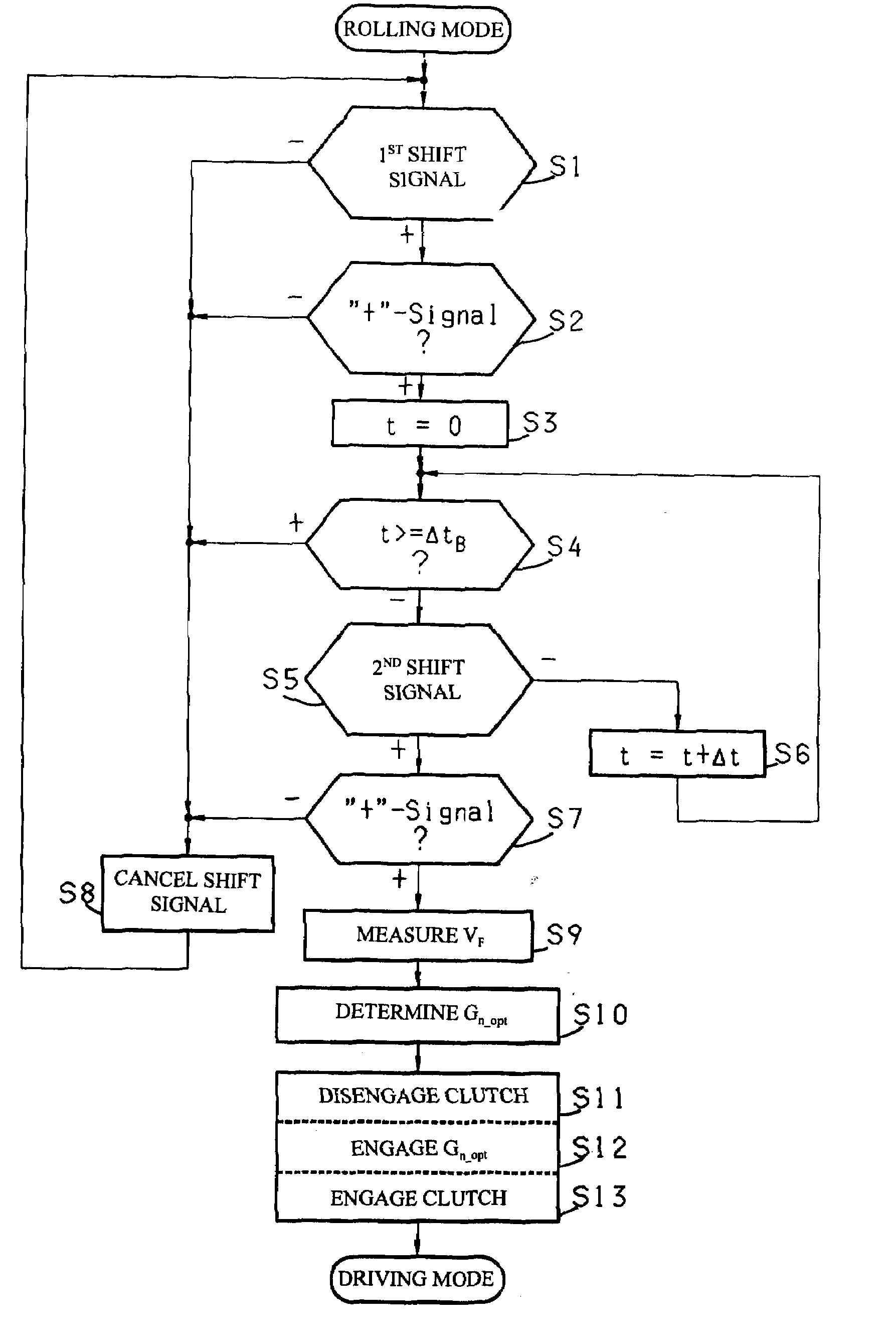
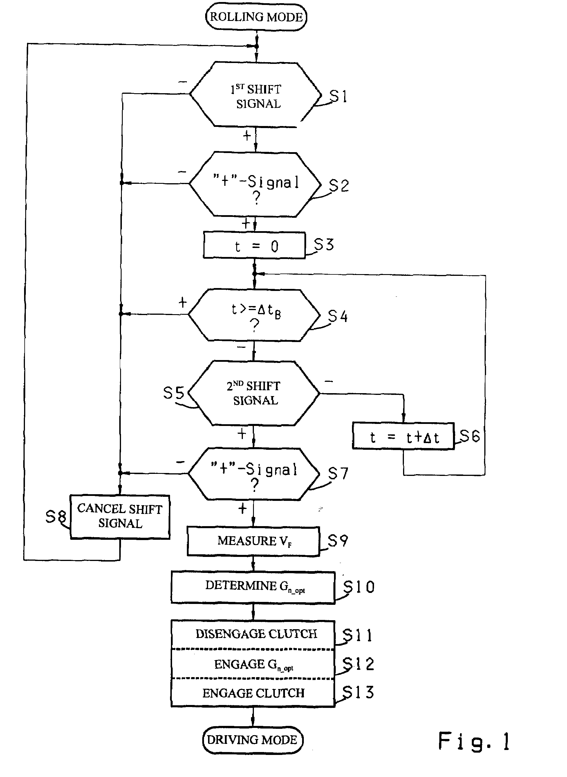
[0030]The process for controlling an automated motor vehicle drivetrain, represented in a simplified variant as an example in FIG. 1, is used when the said vehicle is rolling with its drivetrain disengaged, i.e., when its travel speed VF>0, and when engagement of the drivetrain should be initiated by actuating the selector lever. Since, in the present case, it is assumed that the separating clutch is of the passive-engaging type, such as a diaphragm spring clutch, which is arranged in the force flow between the drive motor and the transmission and which is engaged in its unactuated, rest position, the transmission is then in its neutral position, i.e., no gear is engaged.

[0031]In a rolling mode of the drivetrain control system, it is first checked in step S1 whether a first shift signal produced by actuating an associated selector lever is present. If so, it is checked in the next step S2 whether the signal concerned is for an upshift (“+” signal), i.e., whether the selector lever w...


PUM


Abstract

The invention concerns a method for controlling a motor vehicle drivetrain which comprises a drive motor, a multi-step, automated change-speed transmission and an automated separating clutch arranged between the drive motor and the transmission, and a shifting device with a selector lever which can be moved at least from a particular position in an upshift direction (“+” direction) for manually initiating an upshift and in a downshift direction (“−”) for manually initiating a downshift, and in which the transmission and the separating clutch can be controlled by a transmission control unit which is connected at least to a speed sensor, a brake pedal actuation sensor and a selector lever actuation sensor, such that when the motor vehicle is rolling with its drivetrain open the closing of the drivetrain is initiated by actuating the selector lever.To improve the functional safety it is provided that when a first movement of the selector lever in a shift direction (“+” direction or “−” direction) is sensed, this is interpreted as a provisional command to close the drivetrain, and if a second movement of the selector lever in the same shift direction (“+” direction or “−” direction) is sensed within a specified confirmation time (ΔtB), this is interpreted as a confirmation of the provisional command to close the drivetrain and, as an implementation command, initiates the closing of the drivetrain.

Description

[0001]This application claims priority from German patent application serial no. 10 2008 042 959.7 filed Oct. 20, 2008.FIELD OF THE INVENTION[0002]The invention concerns a method for controlling a motor vehicle drivetrain which comprises a drive motor, a multi-step automated change-speed transmission, an automated separating clutch arranged in the force flow between the drive motor and the transmission, and a shifting device with a selector lever that can be moved at least to a particular position for manually initiating an upshift, in an upshift direction, and for manually initiating a downshift, in a downshift direction, and in which the change-speed transmission and the separating clutch can be controlled by means of a transmission control unit connected at least to a speed sensor, an actuation sensor of an accelerator pedal and an actuation sensor of the selector lever, such that when the motor vehicle is rolling with its drivetrain disengaged, engagement of the drivetrain is in...

Claims


Application Information

Patent Timeline
IPC IPC(8): G06F19/00F16H59/04
CPCB60W10/02B60W10/06F16H2059/0239Y10T74/2014B60W2540/10F16H59/0204B60W30/182F16H2059/186F16H2061/0488B60W2520/10B60W2540/12B60W10/11B60W30/18072B60W2540/16F16H61/0213
Inventor SAUTER, INGOMORO-OLIVEROS, MELCHORBURKHART, MICHAEL
Owner ZF FRIEDRICHSHAFEN AG
Learn More