Method Of Manufacturing A Crankshaft And A Half-Finished Crankshaft

a technology of crankshaft and crankshaft, which is applied in the field of crankshafts, can solve the problems of increasing strictness and increasing the cost of control

Inactive Publication Date: 2010-04-29
TECHNOMETAL
View PDF3 Cites 14 Cited by
  • Summary
  • Abstract
  • Description
  • Claims
  • Application Information

AI Technical Summary

Benefits of technology

[0012]It is therefore an object of the present invention to provide a method of manufacturing a crankshaft and a half-finished crankshaft, which includes a forming process, a machining process and a mass balance adjustment process and alleviates the task of supervising or watching the forming process while satisfying the requirement of strict product accuracy of the crankshaft.

Problems solved by technology

In the environment with increasingly strict requirement for product accuracy of crankshafts, engineers' efforts for enhancing the product accuracy of crankshafts by strictly controlling the forming process have already reached a limit, and such control becomes more and more costly with increased strictness.

Method used


Image

  • Method Of Manufacturing A Crankshaft And A Half-Finished Crankshaft
  • Method Of Manufacturing A Crankshaft And A Half-Finished Crankshaft
  • Method Of Manufacturing A Crankshaft And A Half-Finished Crankshaft

Examples


Embodiment Construction

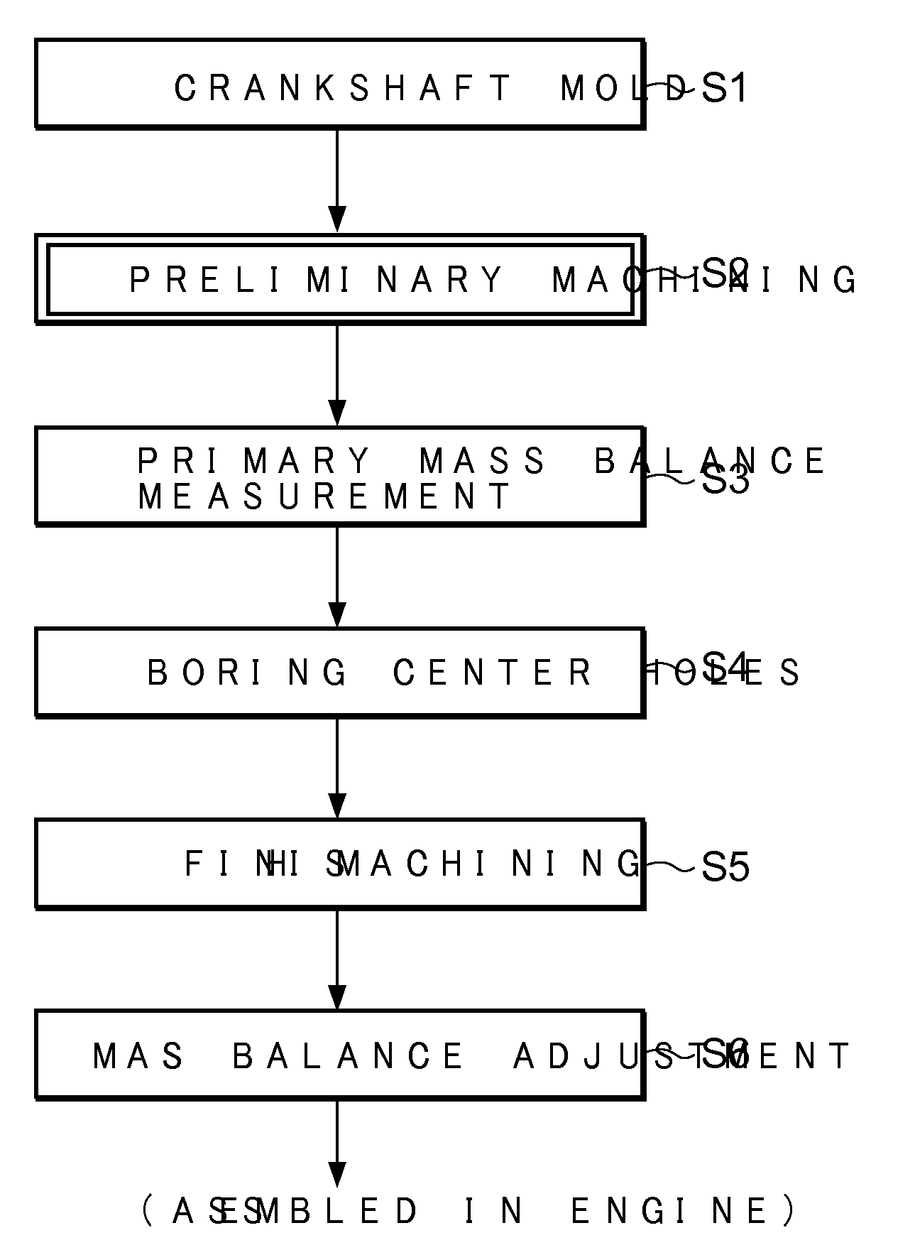
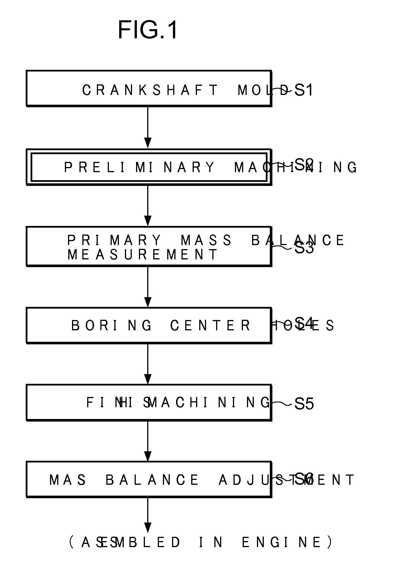
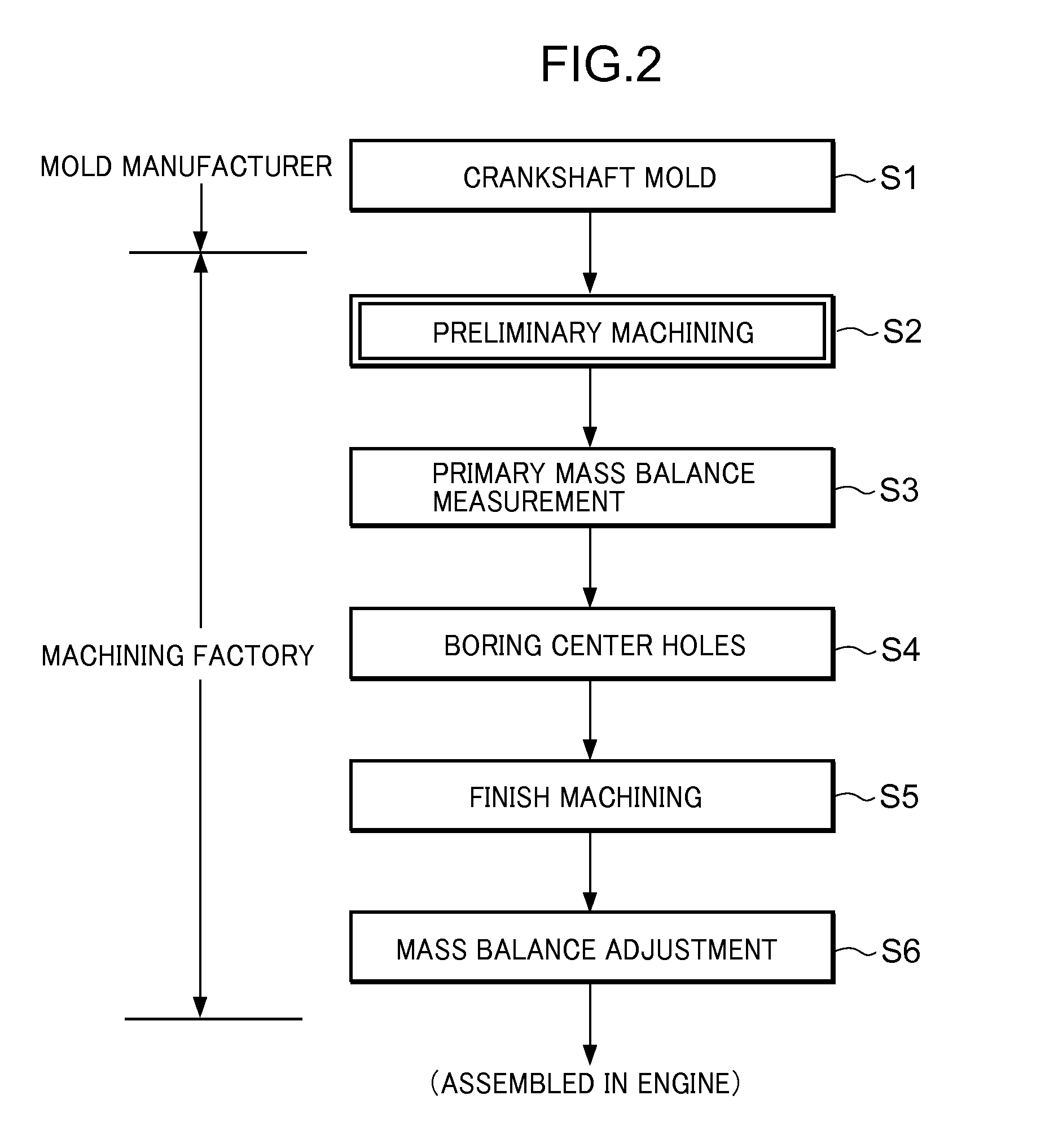
[0034]Preferred embodiments of the present invention will be described below with reference to the attached drawings. FIG. 6 is a flowchart showing a series of steps for manufacturing a forged crankshaft according to a first embodiment of the invention.

[0035]Steps S111 to S119 shown in FIG. 6 make up a process for preparing a half-finished crankshaft from a crankshaft blank. The process for preparing a half-finished crankshaft is carried out in a factory for manufacturing crankshaft molds (hereafter called a mold manufacturing factory as well). As apparent from comparison with FIG. 9 showing an existing manufacturing process, the embodiment of the present invention includes a preliminary machining step S117 interposed before primary mass balance measurement S118. In the preliminary machining step S117, a treated crankshaft mold, which is a ready-to-machine crankshaft stock, is subjected to machining at its balance weight portions. Balance weight portions of the treated crankshaft mo...


PUM

PropertyMeasurementUnit
draft angleaaaaaaaaaa

Abstract

To cope with requirements for strict accuracy of crankshafts while alleviating the task of controlling a forming process, a preliminary machining step (S117) is added before primary mass balance measurement (S118) prior to boring of center holes into opposite end surfaces of a crankshaft mold. In the preliminary machining step (S117), balance weight portions of the crankshaft mold are machined.

Description

CROSS-REFERENCE TO RELATED APPLICATIONS[0001]The present application is a continuation application of PCT / JP2007 / 063627, filed Jul. 3, 2007, which is incorporated herein by reference in its entirety.FIELD OF THE INVENTION[0002]The present invention relates to a crankshaft for use as an engine output shaft, and more particularly, to a method of manufacturing a crankshaft and a half-finished crankshaft.BACKGROUND OF THE INVENTION[0003]Crankshafts for use as engine output shafts are roughly classified to cast crankshafts and forged crankshafts depending on the forming process. Cast crankshafts are mainly used in lower rotation type engines and small engines with relatively small engine torques. Forged crankshafts are used in high rotation type engines and large engines with relatively large torques because they have compact metallographic structure and can be improved in mechanical properties by adding heat treatment after forging, if desired.[0004]Manufacturing of a crankshaft, either...

Claims


Application Information

Patent Timeline
Patent Type & Authority Applications(United States)
IPC IPC(8): B23P17/00
CPCF16C3/08Y10T29/49286G01M1/34F16F15/283B21K1/08B23P15/00B23P2700/07F16C3/20
Inventor MIURA, TETSUO
Owner TECHNOMETAL
Why Eureka
Try Eureka