Diagnostic methods for selective catalytic reduction (SCR) exhaust treatment system

a selective catalytic reduction and exhaust treatment technology, applied in the direction of exhaust treatment electric control, machines/engines, mechanical equipment, etc., can solve the problems of unhealthy nhsub>3/sub>sensors, and the performance of scr catalysts are degraded

Inactive Publication Date: 2010-04-29
DELPHI TECH INC
View PDF12 Cites 63 Cited by
  • Summary
  • Abstract
  • Description
  • Claims
  • Application Information

AI Technical Summary

Problems solved by technology

However, for an SCR catalyst that has lost ammonia storage capability, the NH3 sensed feedback exhibits a much larger magnitude, indicating degraded SCR catalyst performance.
Otherwise, where the NH3 concentration does not track the target theta perturbation, the NH3 sensor is unhealthy.

Method used


Image

  • Diagnostic methods for selective catalytic reduction (SCR) exhaust treatment system
  • Diagnostic methods for selective catalytic reduction (SCR) exhaust treatment system
  • Diagnostic methods for selective catalytic reduction (SCR) exhaust treatment system

Examples


Embodiment Construction

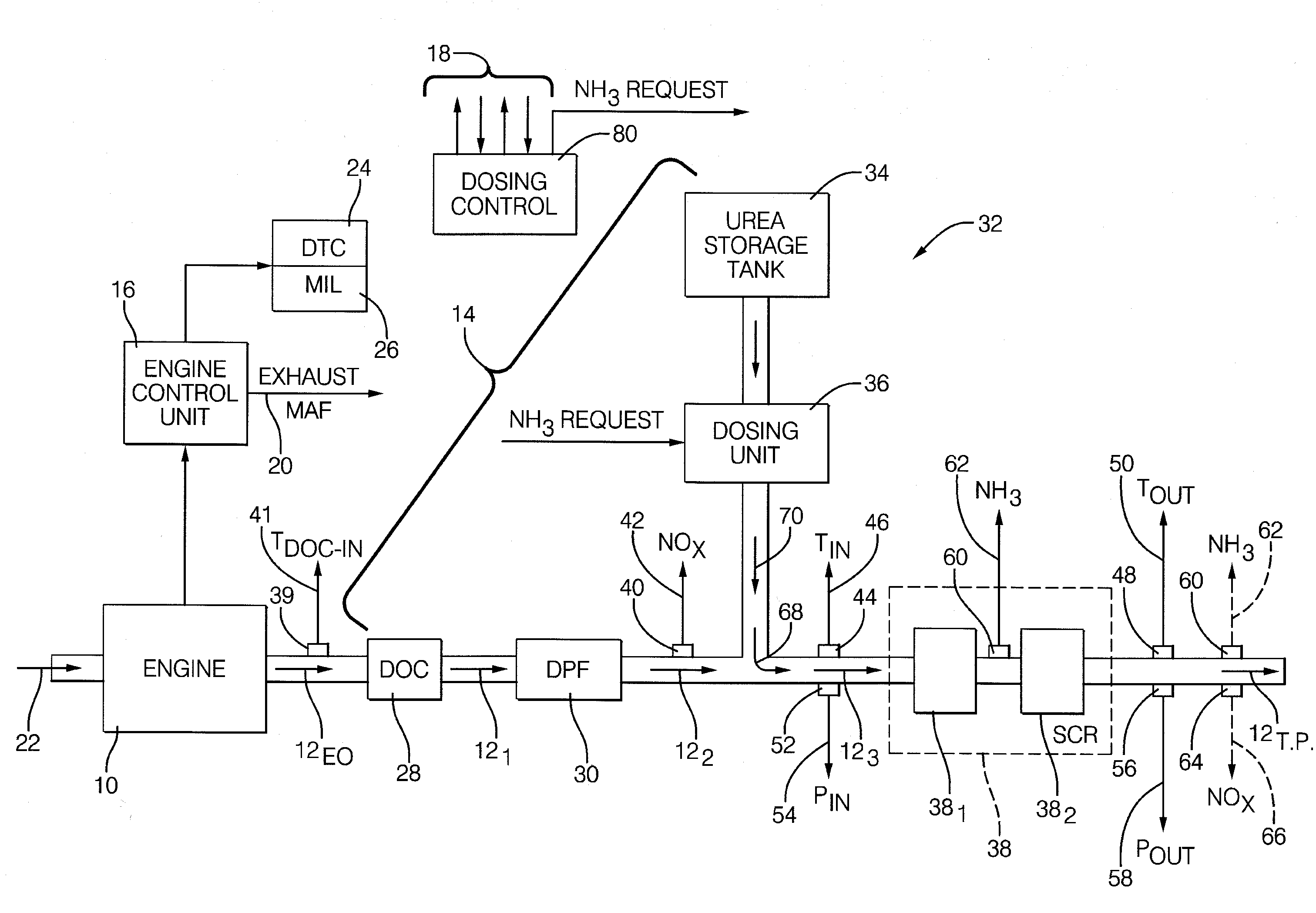
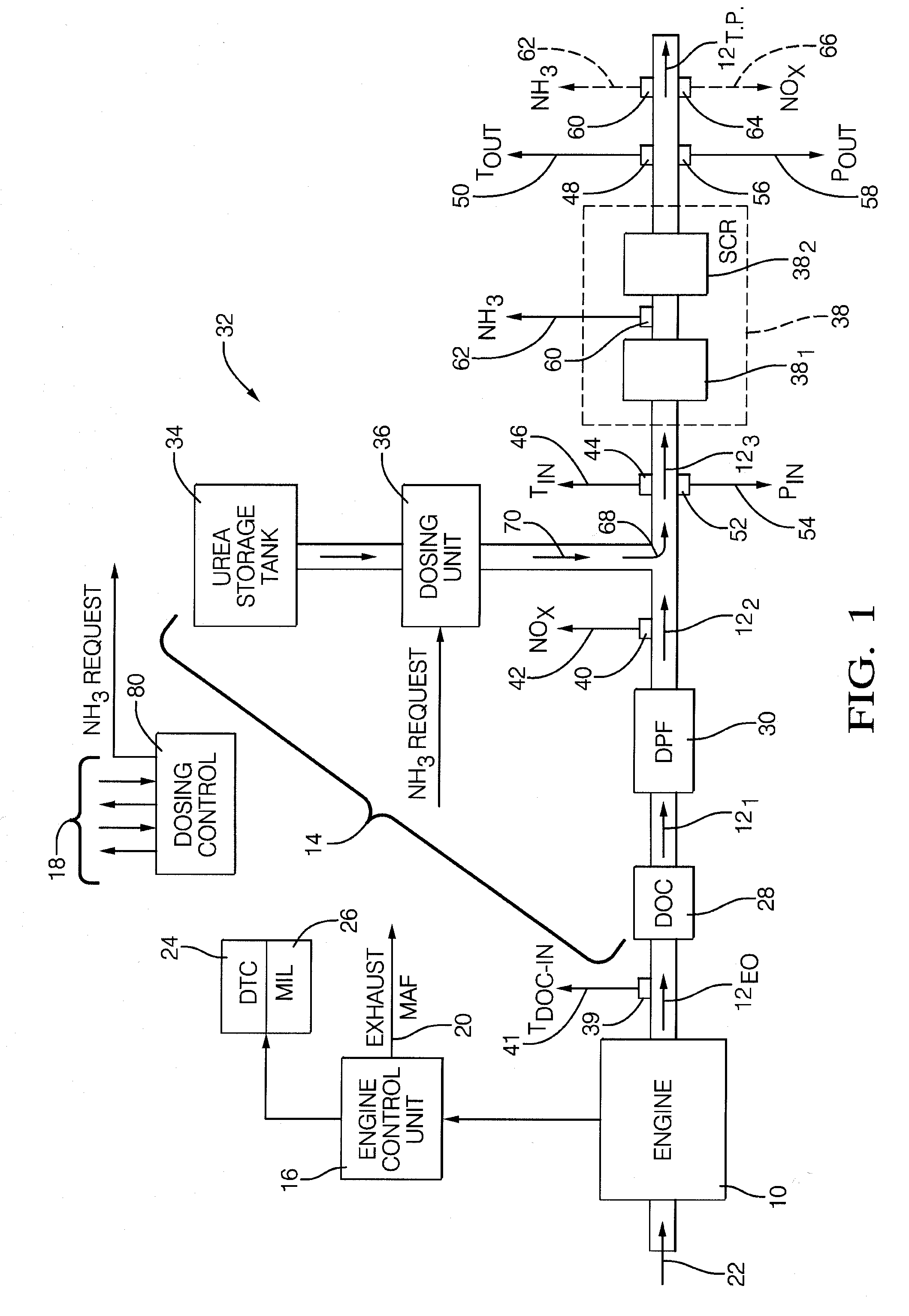
[0024]Referring now to the drawings wherein like reference numerals are used to identify identical components in the various views, FIG. 1 is a diagrammatic and block diagram showing an exemplary diesel cycle internal combustion engine 10 whose combustion exhaust gas 12 is fed to an exhaust gas treatment system 14. The exhaust gas is represented as a stream flowing through the exhaust gas treatment system 14 and is shown as a series of arrows designated 12EO (engine out), 121, 122, 123 and 12TP (tail pipe). It should be understood that while the invention will be described in connection with an automotive vehicle (i.e., mobile) embodiment, the invention may find useful application in stationary applications as well. In addition, embodiments of the invention may be used in heavy-duty applications (e.g., highway tractors, trucks and the like) as well as light-duty applications (e.g., passenger cars). Moreover, embodiments of the invention may find further useful application in various...


PUM


Abstract

In an internal combustion engine system having an exhaust aftertreatment system including a selective catalytic reduction (SCR) catalyst, diagnostic methods involve the intrusive perturbation of a target surface coverage parameter theta to determine the state of health of the SCR catalyst or an ammonia concentration sensor. An adaptive learning block adapts the target theta based on the use of NH3 sensing feedback from a mid-brick positioned ammonia concentration sensor to pull in system variation. A further diagnostic monitors the amount of adaptation and when the adaptive learning excessively learns, the diagnostic assumes that some system-level degradation must have occurred and the diagnostic will notify the overall emissions control monitor.

Description

CROSS-REFERENCE TO RELATED APPLICATIONS[0001]This application claims the benefit of U.S. provisional application Ser. No. 61 / 108,172 filed Oct. 24, 2008 entitled “DIAGNOSTIC METHODS FOR SELECTIVE CATALYTIC REDUCTION (SCR) EXHAUST TREATMENT SYSTEM and EXHAUST GAS TREATMENT SYSTEM AND METHODS FOR OPERATING THE SAME” (attorney Docket No. DP-318283), the disclosure of which is hereby incorporated by reference in its entirety.TECHNICAL FIELD[0002]The present invention relates generally to diagnostics and more particularly to diagnostic methods for selective catalytic reduction (SCR) based engine exhaust treatment systems.BACKGROUND OF THE INVENTION[0003]The relevant background includes the fields of exhaust gas treatment systems and diagnostics therefore. As to the former field of endeavor, there have been a variety of exhaust gas treatment systems developed in the art to minimize emission of undesirable constituent components of engine exhaust gas. It is known to reduce NOx emissions us...

Claims


Application Information

Patent Timeline
Patent Type & Authority Applications(United States)
IPC IPC(8): F01N11/00
CPCF01N3/208Y02T10/24F01N9/005F01N11/00F01N11/002F01N2550/02F01N2560/021F01N2570/18F01N2610/02F01N2610/146F01N2900/0402F01N2900/0408F01N2900/0411F01N2900/0412F01N2900/14F01N2900/1402F01N2900/1621F01N2900/1622Y02T10/47F01N9/00Y02T10/12Y02T10/40
Inventor HERMAN, ANDREW D.WU, MING-CHENGCABUSH, DAVID D.
Owner DELPHI TECH INC
Why Eureka
Try Eureka