Pressure regulator for hydrogen storage system

a technology of pressure regulator and hydrogen storage system, which is applied in the direction of fluid pressure control, process and machine control, etc., can solve the problems of ineffective o-ring seals made of elastomers, silicon is not an appropriate sealing material for hydrogen use, and the hydrogen temperature travelling from a hydrogen storage system to a fuel cell can drop to 80° c, etc., to achieve efficient operation

Inactive Publication Date: 2010-04-29
GM GLOBAL TECH OPERATIONS LLC
View PDF14 Cites 21 Cited by
  • Summary
  • Abstract
  • Description
  • Claims
  • Application Information

AI Technical Summary

Benefits of technology

[0006]Concordant and consistent with the present invention, a pressure regulator for a hydrogen storage system, wherein the pressure regulator is adapted to efficiently operate at temperatures below −50° C., while minimizing the need for separate sealing elements and O-rings, has surprisingly been discovered.

Problems solved by technology

As described in Larson, an elastomer such as ethylene propylene rubber (EPDM) may be suitable for temperatures approaching −50° C. However, the temperature of the hydrogen travelling from a hydrogen storage system to a fuel cell can decrease to values as low as −80° C. Because of the lower temperatures, O-ring seals made of an elastomer are no longer effective.
However, silicon is not an appropriate sealing material for use with hydrogen, as silicon does not have a desirable permeability and is pourous to hydrogen.

Method used


Image

  • Pressure regulator for hydrogen storage system
  • Pressure regulator for hydrogen storage system
  • Pressure regulator for hydrogen storage system

Examples


Embodiment Construction

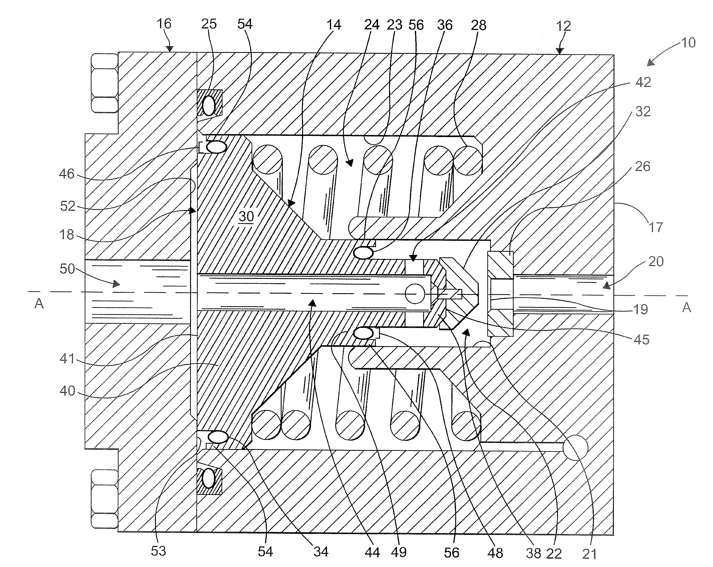
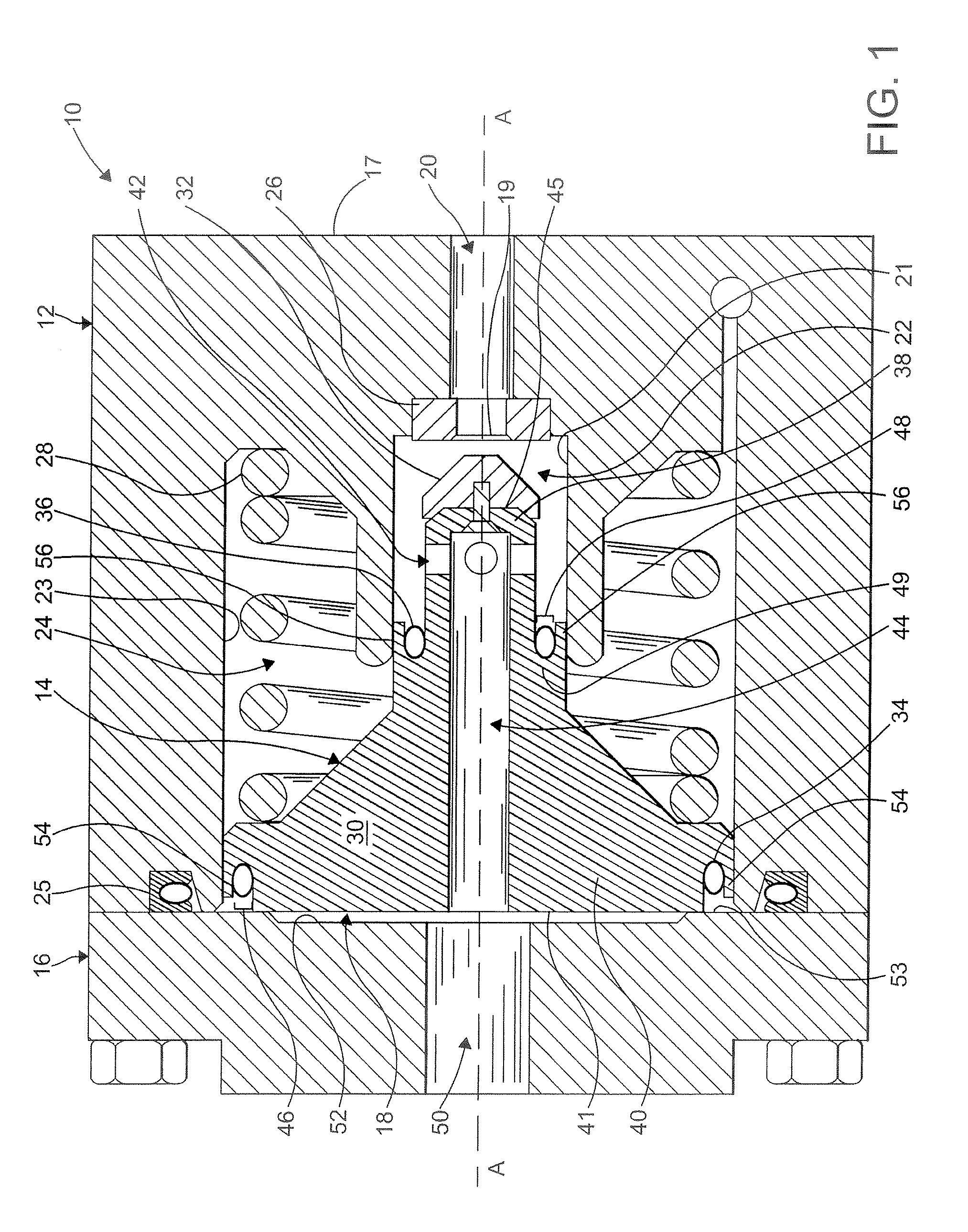
[0016]The following detailed description and appended drawings describe and illustrate various embodiments of the invention. The description and drawings serve to enable one skilled in the art to make and use the invention, and are not intended to limit the scope of the invention in any manner.

[0017]FIGS. 1 and 2 show a pressure regulator 10 for a gas dispensing system (not shown) according to an embodiment of the present invention. As shown, the pressure regulator 10 includes a substantially unitary main body 12, an interior piston assembly 14 disposed within the main body 12, and an end cap 16 coupled to the main body 12, thereby enclosing the piston assembly 14 to form an outlet pressure chamber 18 for pressure control. In FIG. 1 the pressure regulator 10 is shown in a fully opened position. In FIG. 2, the pressure regulator 10 is shown in a fully closed position. Although FIGS. 1 and 2 illustrate an in-line pressure regulator 10, the invention can be applied to other piston-base...


PUM


Abstract

A pressure regulator for a hydrogen storage system, wherein the pressure regulator is adapted to operate at temperatures below −50° C., while minimizing the need for separate sealing elements and O-rings. The pressure regulator includes a main body including an inner cavity bounded by an interior wall, a piston disposed in the inner cavity, the piston including a first channel disposed adjacent a first portion, wherein the first portion is adapted to cooperate with the interior wall to form a seal between the piston and the interior wall, a first biasing device disposed in the first channel, wherein the first biasing device is adapted to exert a force on the first portion of the piston to form a seal between the first portion and the interior wall, and an end cap coupled to the main body thereby enclosing the piston to form an outlet pressure chamber.

Description

FIELD OF THE INVENTION[0001]The present invention relates to pressure regulators. More particularly, the invention is directed to a pressure regulator for a hydrogen storage system.BACKGROUND OF THE INVENTION[0002]Hydrogen in storage systems is typically held at pressures ranging from 20 to 875 bar. However, hydrogen is delivered to a user, e.g. a fuel cell, at lower pressures in the range of 6 to 10 bar, for example. In order to efficiently deliver the hydrogen to the user at a desired pressure, a pressure regulator is needed. Accordingly, there are multiple pressure regulators that may be used. Where the pressure regulator includes a piston for sensing and regulating pressure, seals are required. In certain applications, such as fuel cell systems for example, seals are required to withstand temperature variations in a range of −80° C. and +85° C.[0003]U.S. Pat. App. Pub. No. 2008 / 0011361 to Larson discloses a pressure regulator including O-ring seals formed from an elastomer. As d...

Claims


Application Information

Patent Timeline
Patent Type & Authority Applications(United States)
IPC IPC(8): G05D16/04G05D16/10F16K31/122
CPCF16K17/30F16K31/1221G05D16/103F16K31/1226F16K31/1223Y10T137/7793
Inventor PECHTOLD, RAINERPODORASHI, DEMITRI A.WEIDNER, HANSMARKARD, WOLFGANG
Owner GM GLOBAL TECH OPERATIONS LLC
Why Eureka
Try Eureka