Eureka AIR delivers breakthrough ideas for toughest innovation challenges, trusted by R&D personnel around the world.

Method of transferring pattern of reticle, computer readable storage medium, and method of manufacturing device

Active Publication Date: 2010-04-29
CANON KK
View PDF8 Cites 4 Cited by
  • Summary
  • Abstract
  • Description
  • Claims
  • Application Information

AI Technical Summary

Benefits of technology

[0018]The present invention has been made in consideration of the above-described situation, and accurately, easily determines the illumination condition of a reticle in a lithography process including a step of transferring the pattern of the reticle onto a substrate.

Problems solved by technology

However, from the standpoint of practicality, it would better to form a target pattern by adjusting the exposure apparatus, instead of fabricating another expensive reticle for such a slight modification.
This makes it difficult to partially adjust the NA and undesirably changes the resolving performance.
However, such a process rarely has a physical ground, so the overall matching accuracy at all evaluation points is inevitably decreased.
Such a process rarely has a physical ground as well, so the overall matching accuracy at all evaluation points is again inevitably lowered.
Despite this expectation, the practical application of the calculation result obtained in method 2 is not free from errors due to, for example, computational errors of a resist image used in a mathematical process, and deviations between the numerical definition of the illumination condition and the setting of an actual exposure apparatus.

Method used


Image

  • Method of transferring pattern of reticle, computer readable storage medium, and method of manufacturing device
  • Method of transferring pattern of reticle, computer readable storage medium, and method of manufacturing device
  • Method of transferring pattern of reticle, computer readable storage medium, and method of manufacturing device

Examples


Embodiment Construction

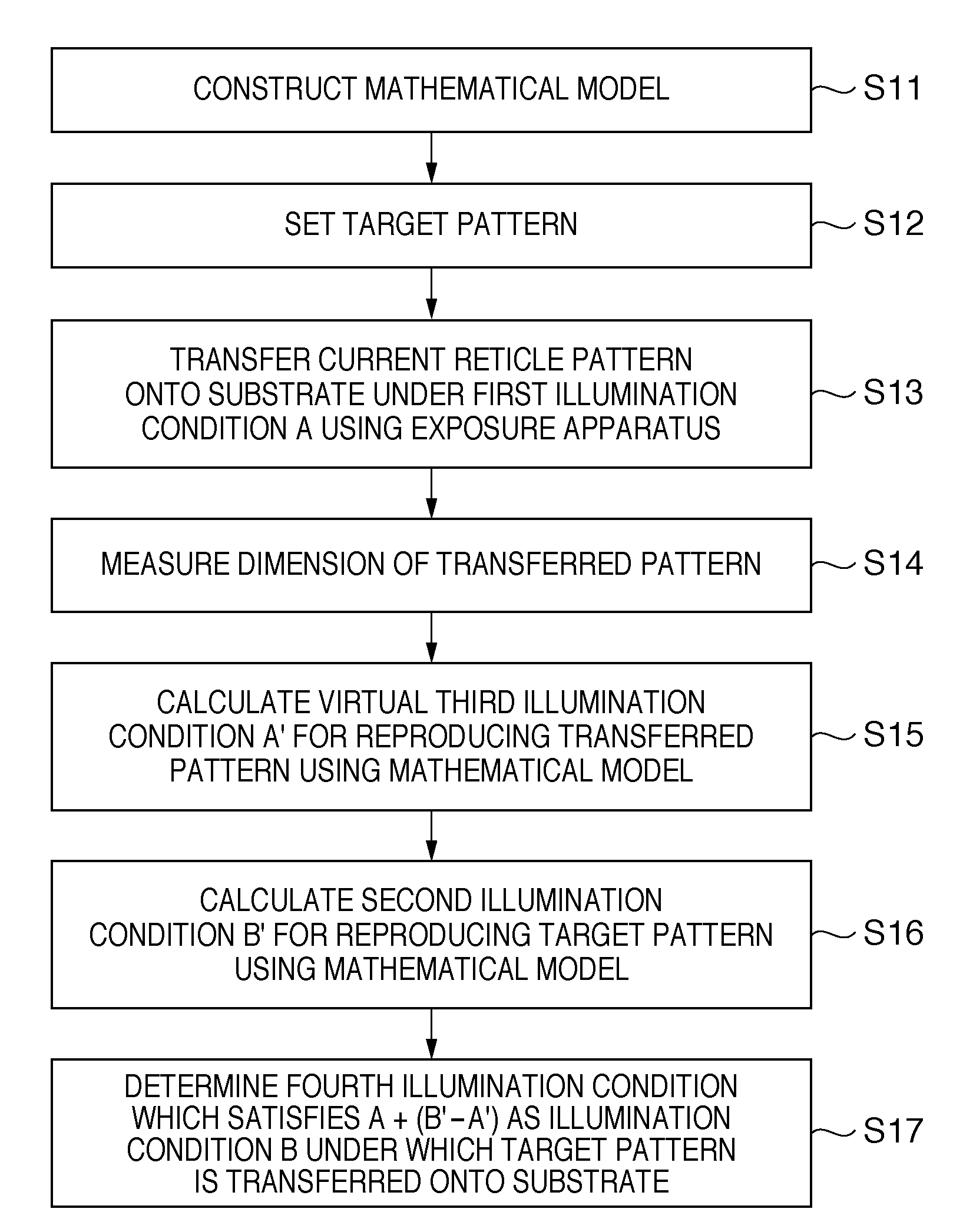
[0037]A method of determining the illumination condition of a reticle in a lithography process including a step of transferring the pattern of the reticle onto a substrate by an exposure apparatus will be described below. Note that the illumination condition includes the light intensity distribution (effective light source) on the pupil plane of an illumination (projection) optical system.

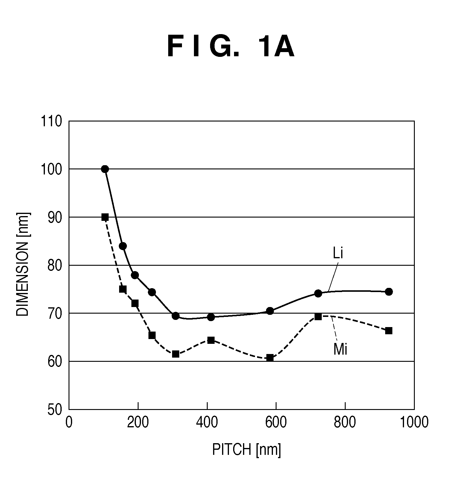
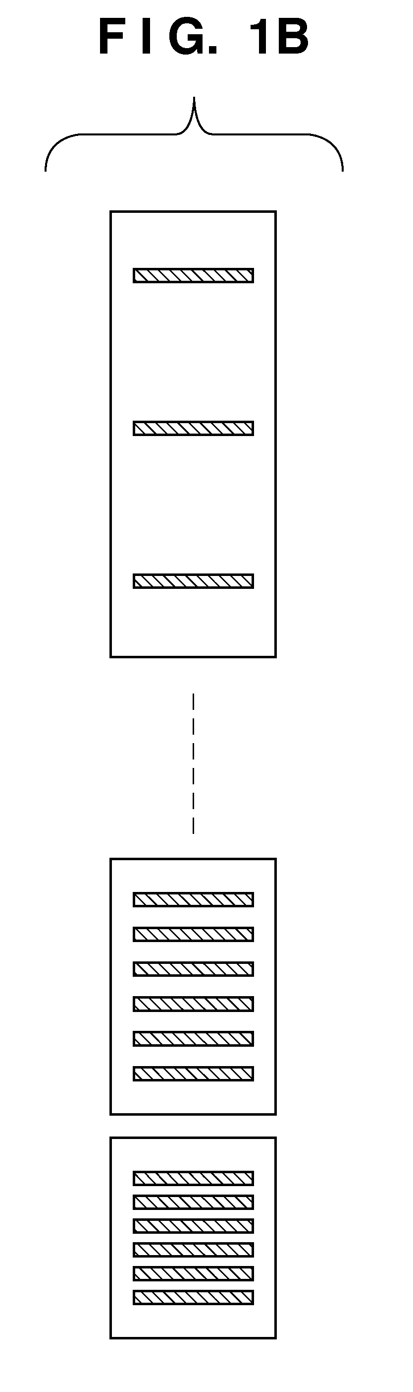
[0038]In a first embodiment, conceptual description will be given first with reference to FIG. 1A. A dotted line in FIG. 1A describes a first pattern (transfer pattern) transferred onto a substrate by actual exposure under a first illumination condition A using a reticle. A solid line in FIG. 1A describes a target pattern to be formed on a substrate using the same reticle as used in the former transfer. In one embodiment, the calculation target is an illumination condition B under which the target pattern is transferred onto a substrate using the same reticle. Note that a plurality of types (e.g., ...


PUM


Abstract

A method includes setting a target pattern to be formed on a substrate using a reticle, obtaining a first pattern using the reticle and a first illumination condition, calculating, a second illumination condition under which the target pattern is transferred onto the substrate using the reticle, and a third illumination condition under which the first pattern is transferred onto a substrate using the reticle, using mathematical models each of which defines the relationship between an illumination condition and a virtual pattern transferred onto a substrate using the illumination condition, determining a fourth illumination condition, obtained by adding the difference between the calculated second illumination condition and third illumination condition to the first illumination condition, as the illumination condition, and transferring the pattern of the reticle onto the substrate by illuminating the reticle using the determined illumination condition.

Description

BACKGROUND OF THE INVENTION[0001]1. Field of the Invention[0002]The present invention relates to a method of transferring a pattern of a reticle onto a substrate, a computer readable storage medium, and a method of manufacturing a device.[0003]2. Description of the Related Art[0004]In a lithography process for manufacturing a semiconductor, predetermined patterning is performed using a reticle (mask). Note, however, that when a new exposure apparatus is introduced into this process, it usually has a performance different from that of the existing exposure apparatus. For this reason, to obtain a transfer pattern identical to that obtained by the conventional exposure apparatus, the new exposure apparatus is to be adjusted.[0005]Also, to improve the device characteristics, the current transfer pattern may be slightly modified. Ideally, in this case, it would be tempted to fabricate another reticle suited to that improvement. However, from the standpoint of practicality, it would bette...

Claims


Application Information

Patent Timeline
IPC IPC(8): G21K5/10
CPCG03F7/70141G03F7/70625G03F7/705
Inventor TSUJITA, KOUICHIROUMIKAMI, KOJIISHII, HIROYUKI
Owner CANON KK
Why Eureka
Eureka Blog
Learn More