Grooved transition coupling

a transition coupling and groove technology, applied in the field of pipe systems, can solve the problems of bulkier and less flexible gaskets, less flexible gaskets, and inability to use the same sliding operation with gaskets with different sizes, so as to facilitate the assembly of pipes and facilitate the insertion of smaller pipes

Inactive Publication Date: 2010-04-29
TYCO FIRE PRODS LP
View PDF8 Cites 46 Cited by
  • Summary
  • Abstract
  • Description
  • Claims
  • Application Information

AI Technical Summary

Benefits of technology

[0007]The transition coupling of the preferred embodiment joins two pipes having different outer diameters. The coupling includes a gasket that functions as a seal by providing three axially-aligned flanges that extend inwardly from a gasket wall to form a triple seal. The flanges at each end of the gasket form separate seals against each of the pipes, and the middle flange forms a seal against the outer diameter surfaces of one or both of the pipes. The gasket facilitates the assembly of the pipes with the middle flange, which has a stepped structure that can be fitted entirely over the outer diameter surface of the larger pipe to form a seal on the larger pipe, and which places the gasket in a first distended state that causes the di

Problems solved by technology

However, for the gasket, which is typically made of an polymer, the extension is substantial and may result in a weaker gasket structure that is more susceptible to failure from forces generated by internal pressures within the pipes.
Typically, this weaker side of the gasket is reinforced with stiffening struts formed within the gasket extension, but the formation of such struts results in a bulkier and less flexible gasket.
However, when joining two differently-sized pipes, the same sliding operation cannot be used with a gasket having differently-sized ends.
If the large end of the gasket is placed on the large pipe first, the entry of the small pipe into the small end of the gasket is impeded because of the interference fit, and the extension between the wall and the opening at the smaller end of the gasket distorts th

Method used


Image

  • Grooved transition coupling
  • Grooved transition coupling
  • Grooved transition coupling

Examples


Embodiment Construction

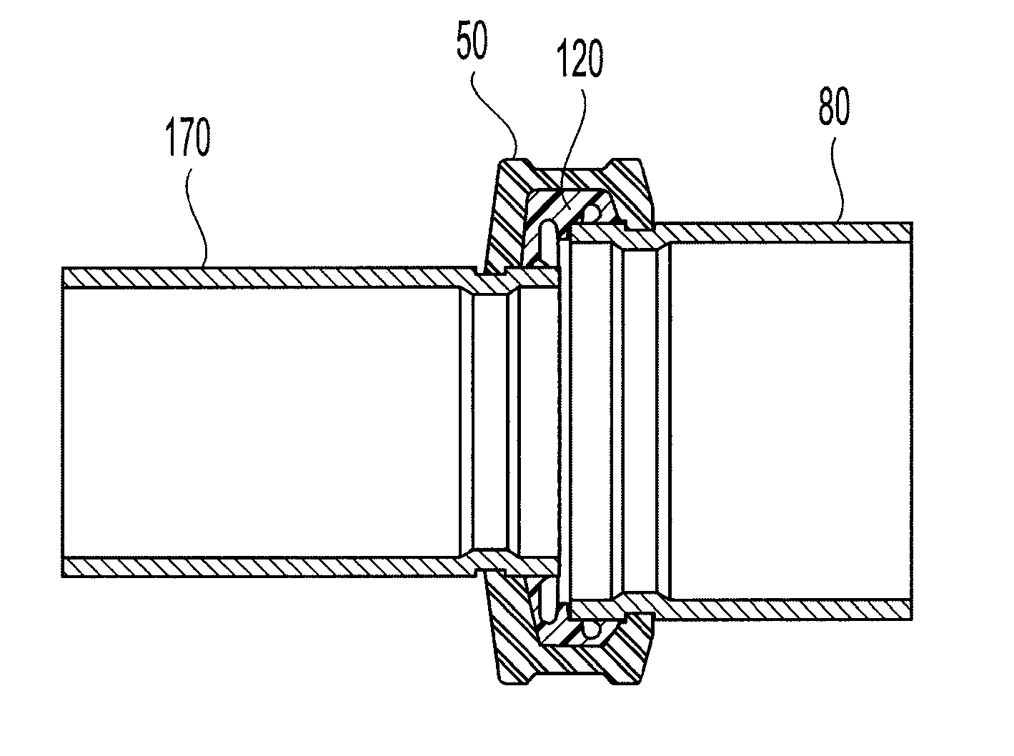
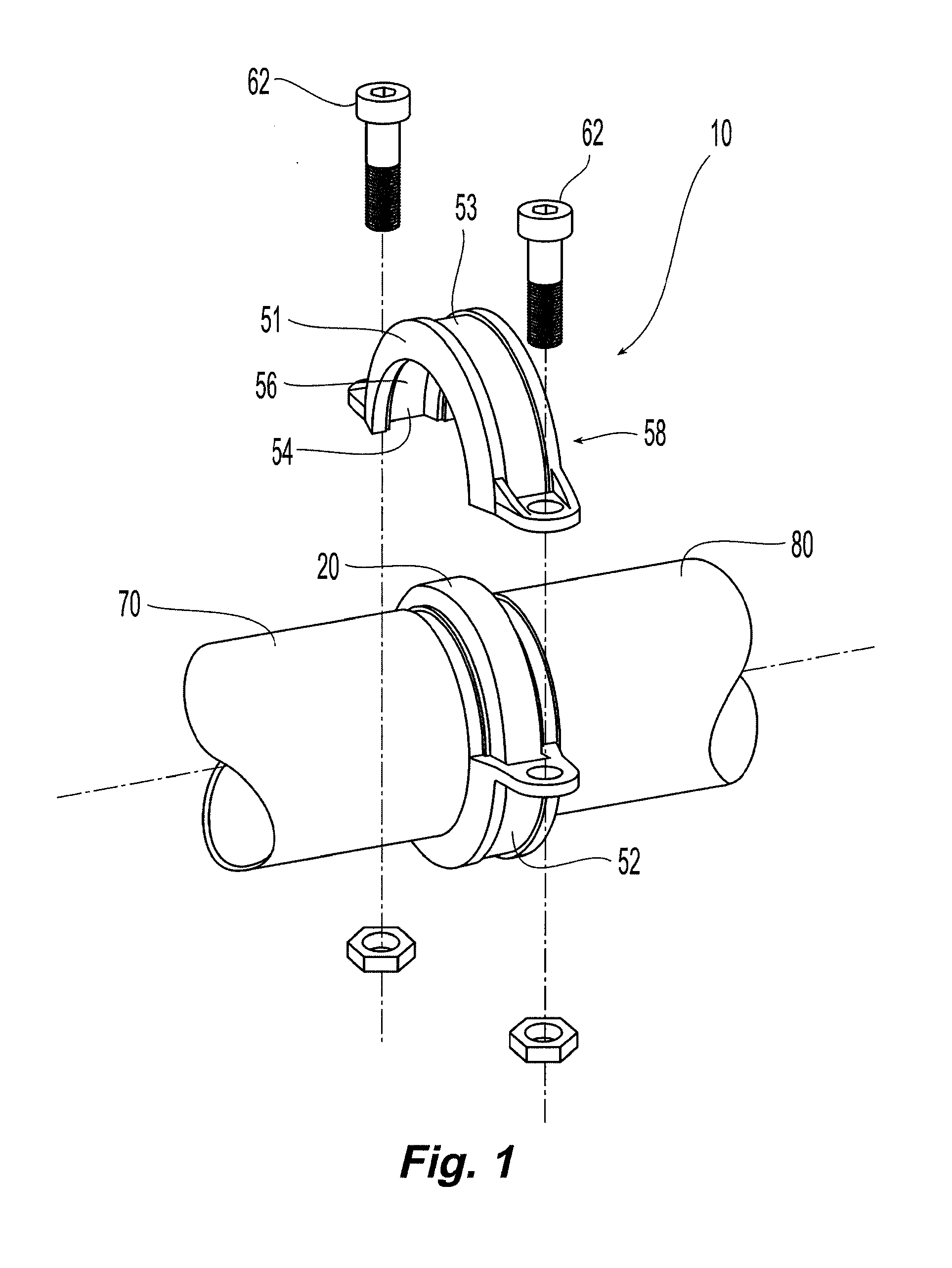
[0025]The transition coupling of the preferred embodiment includes a gasket and coupling that joins together an end of a pipe with a relatively large outer diameter to an end of a pipe with a relatively small outer diameter. The gasket provides a seal between the two differently-sized pipes, and provides a structure for distending an end of the gasket to facilitate the insertion of the smaller pipe into the gasket during assembly. The gasket also provides for a preferred method of joining the pipes that involves distending one end of the gasket to permit insertion of the smaller pipe into the gasket.

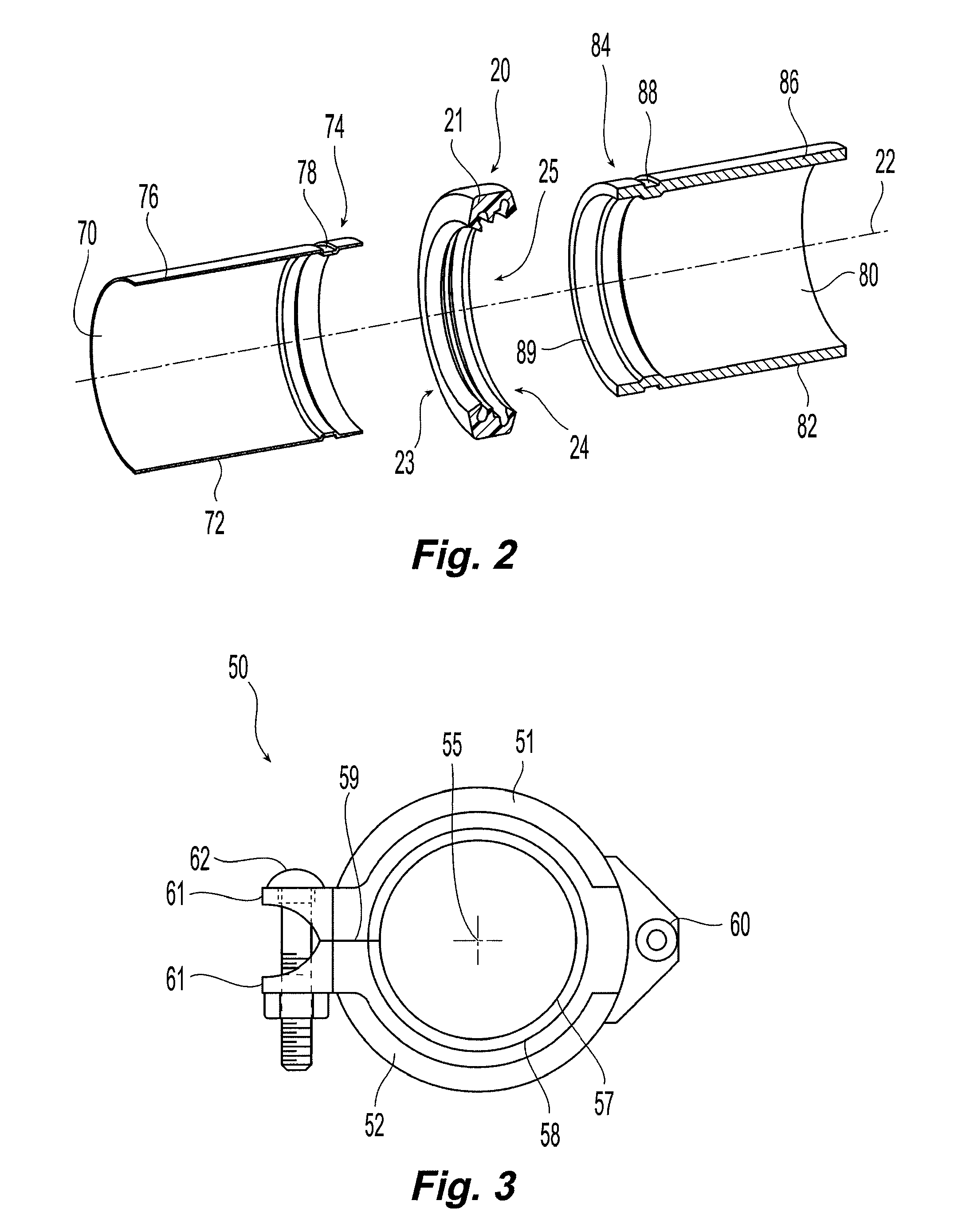
[0026]As illustrated in FIG. 1, a transition coupling 10 preferably includes a gasket 20 and a coupling 50, which join together a small diameter pipe 70 and a large diameter pipe 80. As illustrated in FIG. 2, the gasket 20 has a circumferential wall 21 that defines a central axis 22 and a small open end 23 and a large open end 24, and a channel 25 between the open ends 23 and 24.

[0027]Th...


PUM

PropertyMeasurementUnit
Lengthaaaaaaaaaa
Lengthaaaaaaaaaa
Lengthaaaaaaaaaa

Abstract

A pipe coupling and gasket, a pipe coupling system, and installation method for joining and sealing adjoining pipes having different outer diameters. The gasket including three flanges extending radially inward, with the middle flange acting as a fulcrum against the outer surface of the larger pipe to cause distension of the opening of the gasket receiving the smaller pipe, to permit easy entry of the smaller pipe into the gasket. The gasket is then slid over the larger pipe so that the middle flange slips over the edge of the larger pipe to relax the opening of the gasket receiving the smaller pipe. The middle flange can also form a sealing surface on the outer diameter surfaces of the larger pipe or on both the larger and smaller pipes. The middle flange can also form a sealing surface against the radially extending end surface of the larger pipe.

Description

PRIORITY DATA AND INCORPORATION BY REFERENCE[0001]This application claims the benefit of priority under 35 U.S.C. 119(e) to U.S. Provisional Patent Application No. 60 / 869,194, filed Dec. 8, 2006, which is incorporated by reference in its entirety.TECHNICAL FIELD[0002]The subject invention relates to piping systems and, more particularly, to couplings and gaskets joining components of piping systems.BACKGROUND ART[0003]Pipe coupling gaskets are commonly used with pipe couplings to seal adjoining pipes, with each end of the coupling-gasket assembly sized to fit to the end of each pipe. Typical designs of pipe coupling gaskets have a U-shaped cross section with a wall and two ends extending inwardly from the wall to form gasket ends that, when installed, fit over each end of two adjoining pipes with an interference fit, i.e., the inner diameters of the openings in the ends of the gasket are naturally smaller than the outer diameters of the pipes. The interference fit between the pipes ...

Claims


Application Information

Patent Timeline
IPC IPC(8): F16L17/00B23P11/00
CPCF16L17/04Y10T29/49826F16L25/14F16L21/065
Inventor RADZIK, JOSEPH G.
Owner TYCO FIRE PRODS LP
Why Eureka
Try Eureka