Lighting device which includes one or more solid state light emitting device

a technology of light emitting device and light emitting device, which is applied in the direction of discharge tube luminescnet screen, discharge tube main electrode, incadescent cooling arrangement, etc., can solve the problems of many solid state light emitters that do not operate well in high temperatures, and the heat generated by light sources is trapped inside, so as to reduce heat loss or cooling loss

Active Publication Date: 2010-04-29
IDEAL IND LIGHTING LLC
View PDF29 Cites 79 Cited by
  • Summary
  • Abstract
  • Description
  • Claims
  • Application Information

AI Technical Summary

Benefits of technology

[0015]In many cases (e.g., most residential applications), fixtures (e.g., “cans”) are required to be substantially airtight around the sides and top to prevent the loss of ambient heat or cooling from the room into the ceiling cavity through the fixture. As the lamp is mounted in the can, much of the heat generated by the light source is trapped within the can, because the air heated in the can rises and is trapped within the can. Insulation is usually required around the can within the ceiling cavity to further reduce heat loss or cooling loss from the room into the ceiling cavity.

Problems solved by technology

Many solid state light emitters, however, do not operate well in high temperatures.
As the lamp is mounted in the can, much of the heat generated by the light source is trapped within the can, because the air heated in the can rises and is trapped within the can.

Method used


Image

  • Lighting device which includes one or more solid state light emitting device
  • Lighting device which includes one or more solid state light emitting device
  • Lighting device which includes one or more solid state light emitting device

Examples


first embodiment

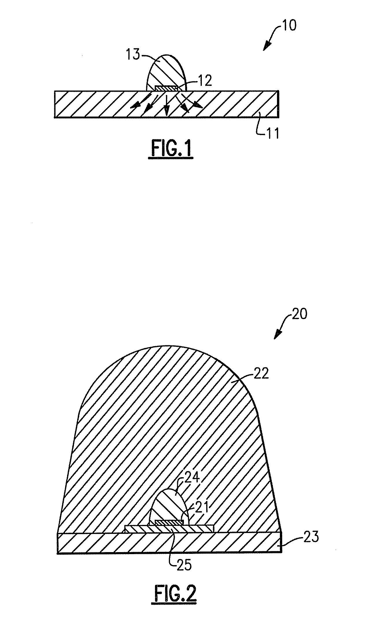
[0102]FIG. 2 depicts a lighting device 20 according to the present inventive subject matter. Referring to FIG. 2, the lighting device 20 comprises a solid state light emitter chip 21, a substantially transparent heat sink 22 formed of a solid material, a heat spreader 23 formed of aluminum, an encapsulant 24 and a printed circuit board 25.

second embodiment

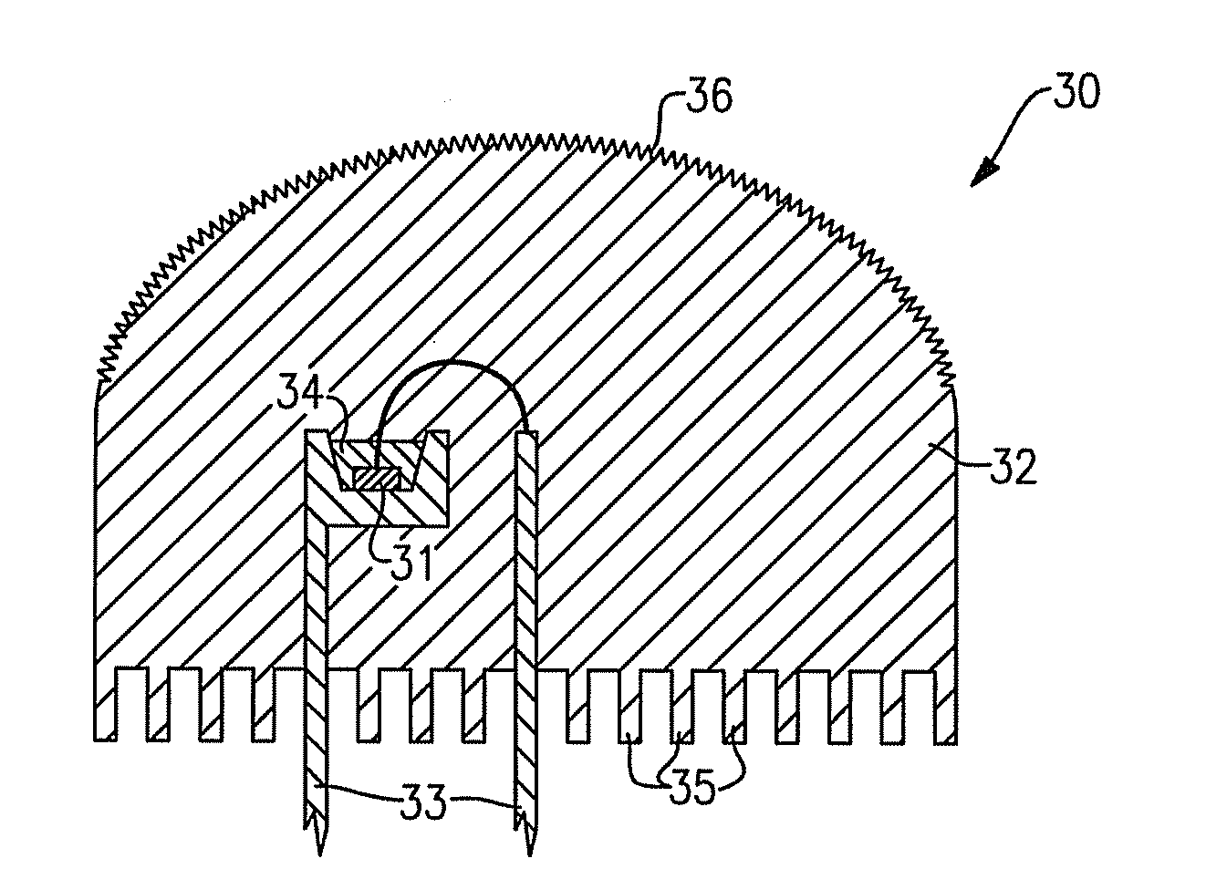
[0103]FIG. 3 depicts a lighting device 30 according to the present inventive subject matter. Referring to FIG. 3, the lighting device 30 comprises a solid state light emitter chip 31, a substantially transparent heat sink 32 formed of a solid material, a leadframe 33 and a lumiphor 34. The substantially transparent heat sink comprises fins 35 and an optical feature 36.

third embodiment

[0104]FIG. 4 depicts a lighting device 40 according to the present inventive subject matter. The lighting device 40 is a back-reflecting lighting device. Referring to FIG. 4, the lighting device 40 comprises a solid state light emitter chip 41, a substantially transparent heat sink 42 formed of a solid material, a back-reflector 43 made of reflective surface material, an encapsulant 44, a negative terminal 45 and a positive terminal 46.

[0105]FIG. 5 is a top view of the lighting device 40 depicted in FIG. 4.


PUM


Abstract

There is provided a lighting device which comprises at least one solid state light emitter and a substantially transparent heat sink. The heat sink and the solid state light emitter are positioned and oriented relative to one another such that if the solid state light emitter is illuminated, light emitted by the solid state light emitter which exits the lighting device passes through at least a portion of the heat sink. Also, there is provided a lighting device which comprises at least one solid state light emitter and means for extracting heat from the solid state light emitter.

Description

CROSS-REFERENCE TO RELATED APPLICATIONS[0001]This application claims the benefit of U.S. Provisional Patent Application No. 61 / 108,130, filed Oct. 24, 2008, the entirety of which is incorporated herein by reference.FIELD OF THE INVENTIVE SUBJECT MATTER[0002]The present inventive subject matter relates to lighting devices. In some embodiments, the present inventive subject matter relates to lighting devices which include one or more solid state light emitting devices, e.g., light emitting diodes.BACKGROUND [0003]A large proportion (some estimates are as high as twenty-five percent) of the electricity generated in the United States each year goes to lighting. Accordingly, there is an ongoing need to provide lighting which is more energy-efficient. It is well-known that incandescent light bulbs are very energy-inefficient light sources—about ninety percent of the electricity they consume is released as heat rather than light. Fluorescent light bulbs are more efficient than incandescent...

Claims


Application Information

Patent Timeline
Patent Type & Authority Applications(United States)
IPC IPC(8): H01J61/52
CPCH01L33/56H01L33/641H01L33/642H01L2224/48247H01L2924/13091H01L2224/48091H01L2924/00014H01L2924/00
Inventor VAN DE VEN, ANTONY PAULNEGLEY, GERALD H.
Owner IDEAL IND LIGHTING LLC
Why Eureka
Try Eureka