Thread, fastening system, pipe fitting and method for manufacturing thread

a technology of fastening system and thread, applied in the direction of threaded fasteners, screw threaded joints, screwed fasteners, etc., can solve the problems of reducing the fastening force, reducing the sealing force, and achieving high sealing properties, so as to prevent loosening of fastened threads, prolong the sealing ability of parts, and inhibit the effect of screw thread deformation over a long period of tim

Inactive Publication Date: 2010-04-29
YUGEN KAISHA HAMA INT
View PDF3 Cites 15 Cited by
  • Summary
  • Abstract
  • Description
  • Claims
  • Application Information

AI Technical Summary

Benefits of technology

[0046]According to the present invention, a thread which is capable of increasing a close contact between threads to be screwed fit with each other to enhance a sealing capability of a fastened part, as well as inhibiting a deformation of screw threads over a long period of time, thus preventing looseness of fastened threads resulting from the deformation, a method for manufacturing the thread, a fastening system using the thread, a pipe fitting using the thread are accomplished.

Problems solved by technology

To prevent looseness over a long period of time with respect to thread parts has been a conventional problem.
However, as described above, in threads which cause anti-looseness action by a combination of dissimilar members (engagement), thread counterpart results in receiving a drag in an axis line direction during fastening operation.
As a result, a problem could arise that dissimilar members frequently introduce mutually positional displacement from each other in an axis line direction, and a fastening force is decreased.
Particularly, not being loosened over a long period of time, as long as they are used in applications where to cause a fluid to pass therethrough, and achieving high sealing properties have become problems.

Method used


Image

  • Thread, fastening system, pipe fitting and method for manufacturing thread
  • Thread, fastening system, pipe fitting and method for manufacturing thread
  • Thread, fastening system, pipe fitting and method for manufacturing thread

Examples


Embodiment Construction

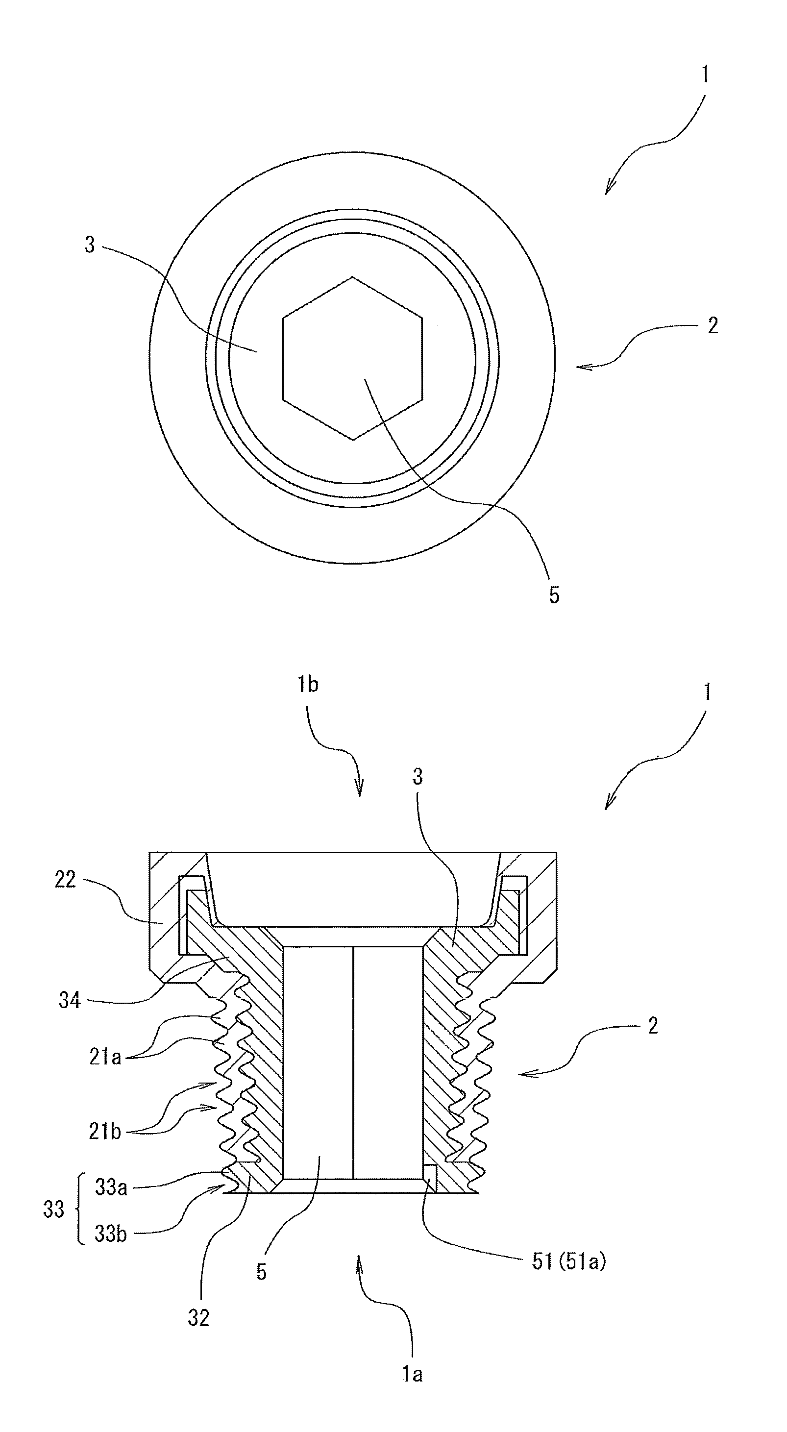
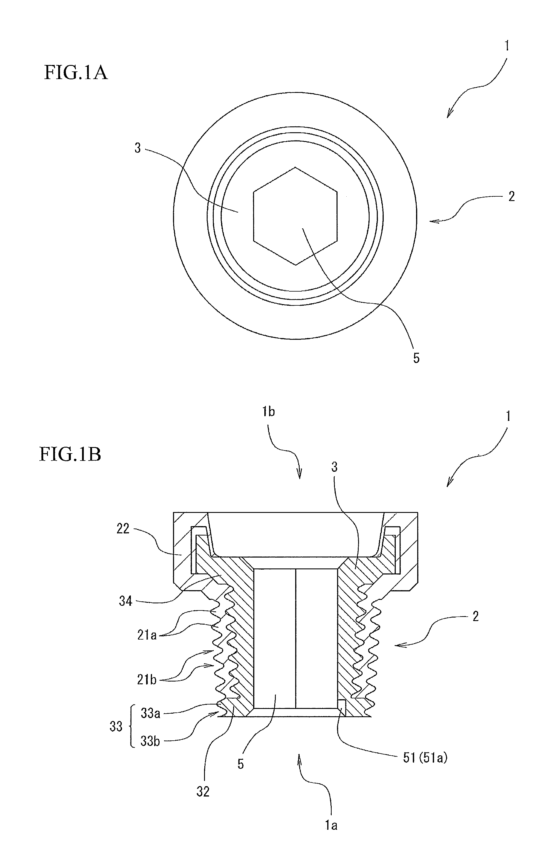
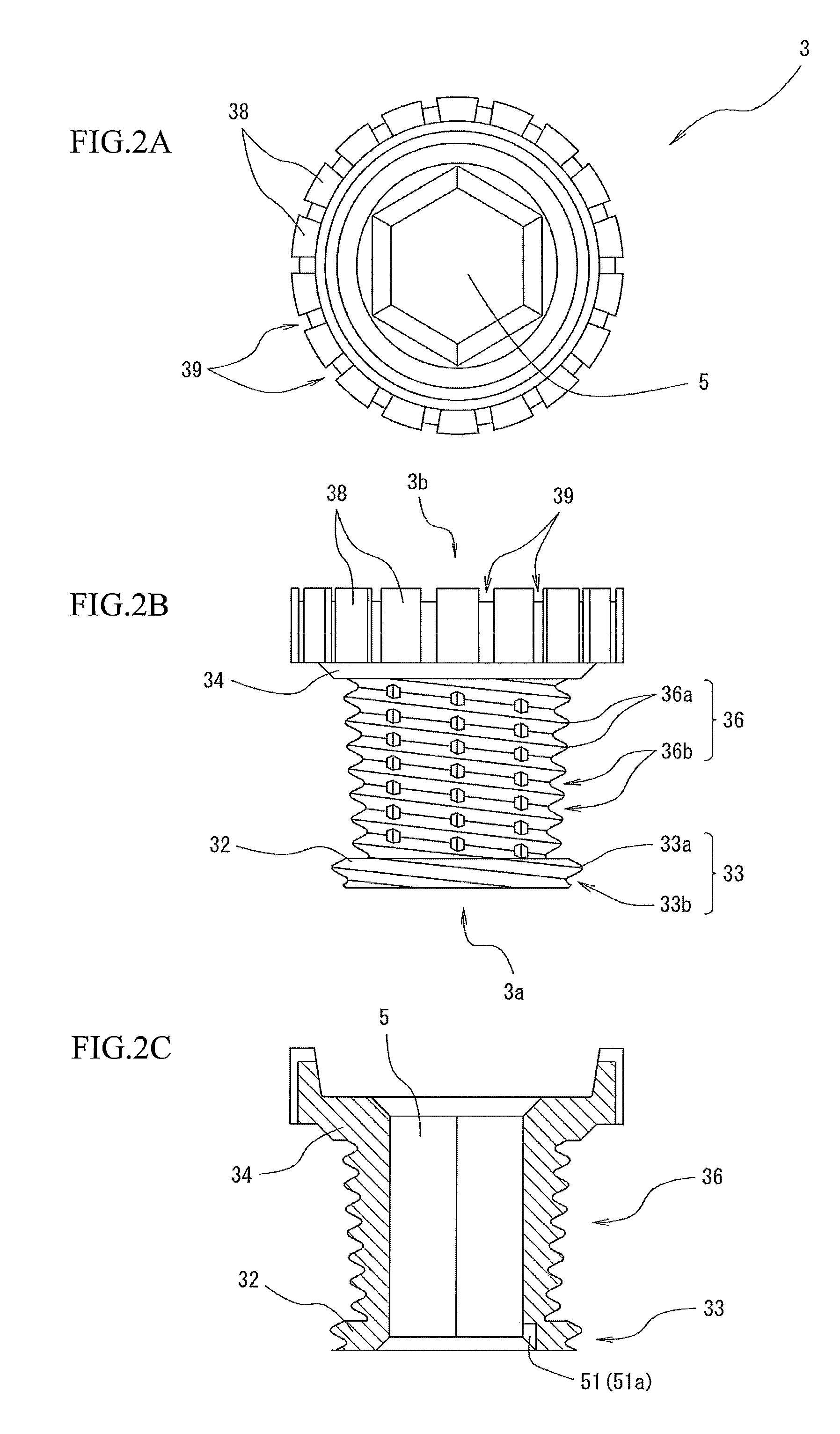
[0055]Hereinafter, exemplary embodiments of the present invention will be described in detail with reference to the drawings. FIG. 1A and FIG. 1B are a schematic view illustrating an example of a thread 1 according to a first exemplary embodiment of the present invention, FIG. 1A is a top plan view, and FIG. 1B is a front elevational sectional view. FIGS. 2A-2C are a schematic view illustrating a configuration of an insert core 3 of the thread 1, FIG. 2 A is a top plan view, FIG. 2B is a front view, and FIG. 2C is a front elevational sectional view. FIG. 3 is an enlarged view illustrating a configuration of a close contacting part between a screw thread member 2 of the thread 1 and an insert core 3. FIG. 4 is an enlarged view illustrating a configuration of an outer periphery part of an insert core 3 of the thread 1. FIG. 5 is a schematic view illustrating a configuration of a pipe fitting 7 having the thread 1. FIG. 6A and FIG. 6B are a schematic view illustrating an example of a t...


PUM

PropertyMeasurementUnit
diameteraaaaaaaaaa
shapeaaaaaaaaaa
elasticityaaaaaaaaaa

Abstract

To provide a thread in which looseness can be prevented over a long period of time, and a high sealing properties can be maintained, a manufacturing method of the thread, a fastening system using the thread, and a pipe fitting using the thread. A thread according to the present invention is provided, wherein, a screw thread member of which screw threads are formed on an outer periphery thereof and which is made up of a softer material than that of an insert core is formed in a close contact with an outer periphery of the insert core, large-diameter parts that sandwich the screw thread member therebetween in an axis line direction are formed, in a fore end part and a rear end part of the insert core or an intermediate part nearer to the fore end part 3a from the rear end part, and screw threads that are continuous to screw threads of the screw thread member are formed on an outer periphery of a large-diameter part of the fore end part.

Description

BACKGROUND OF THE INVENTION[0001]1. Field of the Invention[0002]The present invention relates to a thread, a method for manufacturing the thread, a fastening system and a pipe fitting using the thread.[0003]2. Description of the Related Art[0004]To prevent looseness over a long period of time with respect to thread parts has been a conventional problem.[0005]Similar to threads as described in, for example, Patent Document 1, there is proposed a technique for preventing looseness in such a manner that a deeper groove is formed than a thread root part along an axis line of a leg part, and a anti-loose member made up of a metal wire and a resin material that encapsulates it internally is inserted fitly into the groove, the resin material is deformed to have an elasticity along female-threads, as well as the metal wire is pressed into the groove along female-threads against a bouncing force of the resin material.[0006]As another example, similar to threads as described in Patent Documen...

Claims


Application Information

Patent Timeline
Patent Type & Authority Applications(United States)
IPC IPC(8): F16B35/02B21H3/02
CPCF16B33/006F16L15/06F16B39/30F16B37/122F16B13/12F16B39/00
Inventor HAMA, TOMIOHAMAUE, YUJI
Owner YUGEN KAISHA HAMA INT
Why Eureka
Try Eureka