
Catheter Control Mechanism and Steerable Catheter

a control mechanism and catheter technology, applied in the field of surgical catheters and leads, can solve the problems of uni-directional or bi-directional bending of electrically active catheters, etc., and achieve the effects of convenient manufacture, easy manipulation, and low cos

Active Publication Date: 2010-04-29
OSCOR
View PDF8 Cites 124 Cited by
  • Summary
  • Abstract
  • Description
  • Claims
  • Application Information

AI Technical Summary

Benefits of technology

[0004]Currently, electrophysiology catheters (“EP catheters”) for use in cardiac ablation procedures are only capable of uni-directional or bi-directional bending. There remains a need in the art for a steerable catheter and / or lead structure that more agile in manipulation, durable, inexpensive, and easy to manufacture. There also remains a need in the art for control mechanisms capable of reliably and intuitively controlling such catheters. The present invention provides a solution for these needs.

Problems solved by technology

Currently, electrophysiology catheters (“EP catheters”) for use in cardiac ablation procedures are only capable of uni-directional or bi-directional bending.

Method used


Image

  • Catheter Control Mechanism and Steerable Catheter
  • Catheter Control Mechanism and Steerable Catheter
  • Catheter Control Mechanism and Steerable Catheter

Examples


Embodiment Construction

[0037]Reference will now be made in detail to selected preferred embodiments of the invention, examples of which are illustrated in the accompanying drawings.

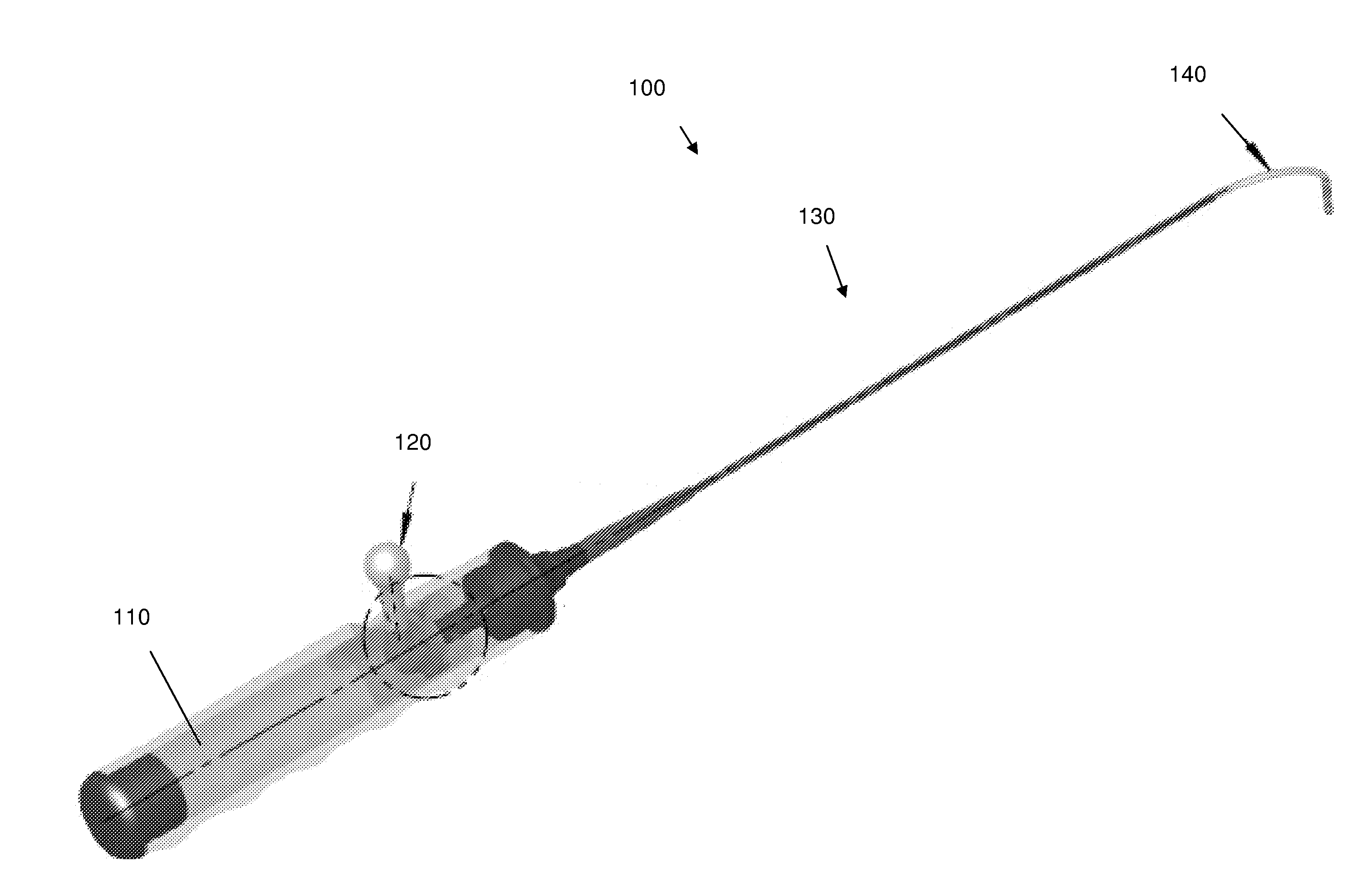
[0038]In accordance with the invention, for the purpose of illustration and not limitation, a steerable catheter lead assembly is shown in FIG. 1, and designated by reference number 100.

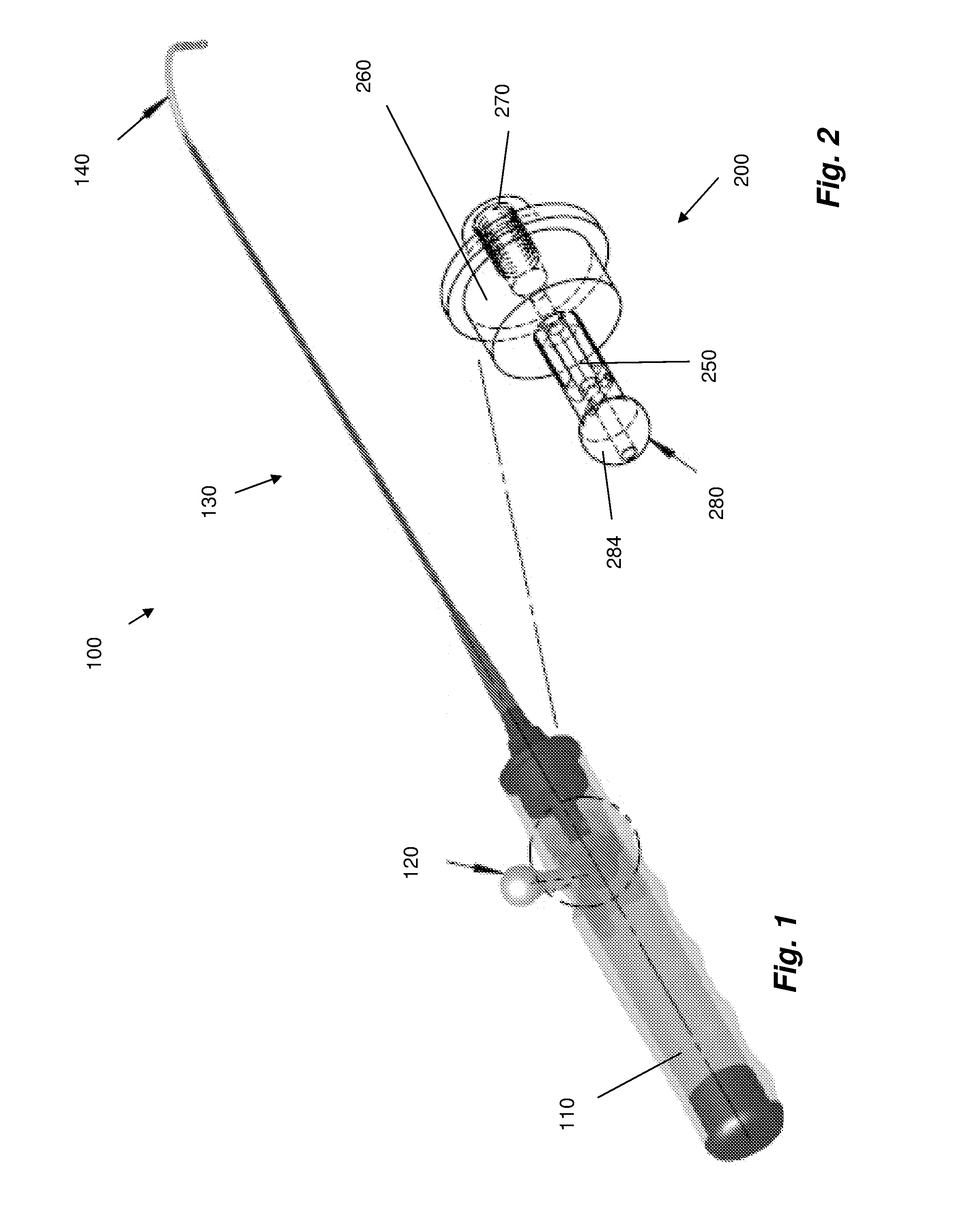
[0039]The steerable lead assembly includes a main handle 110, main shaft 130, steerable distal shaft portion 140 and a control handle 120 operatively connected with a control assembly 200, as best seen in FIGS. 2 and 6, for example.

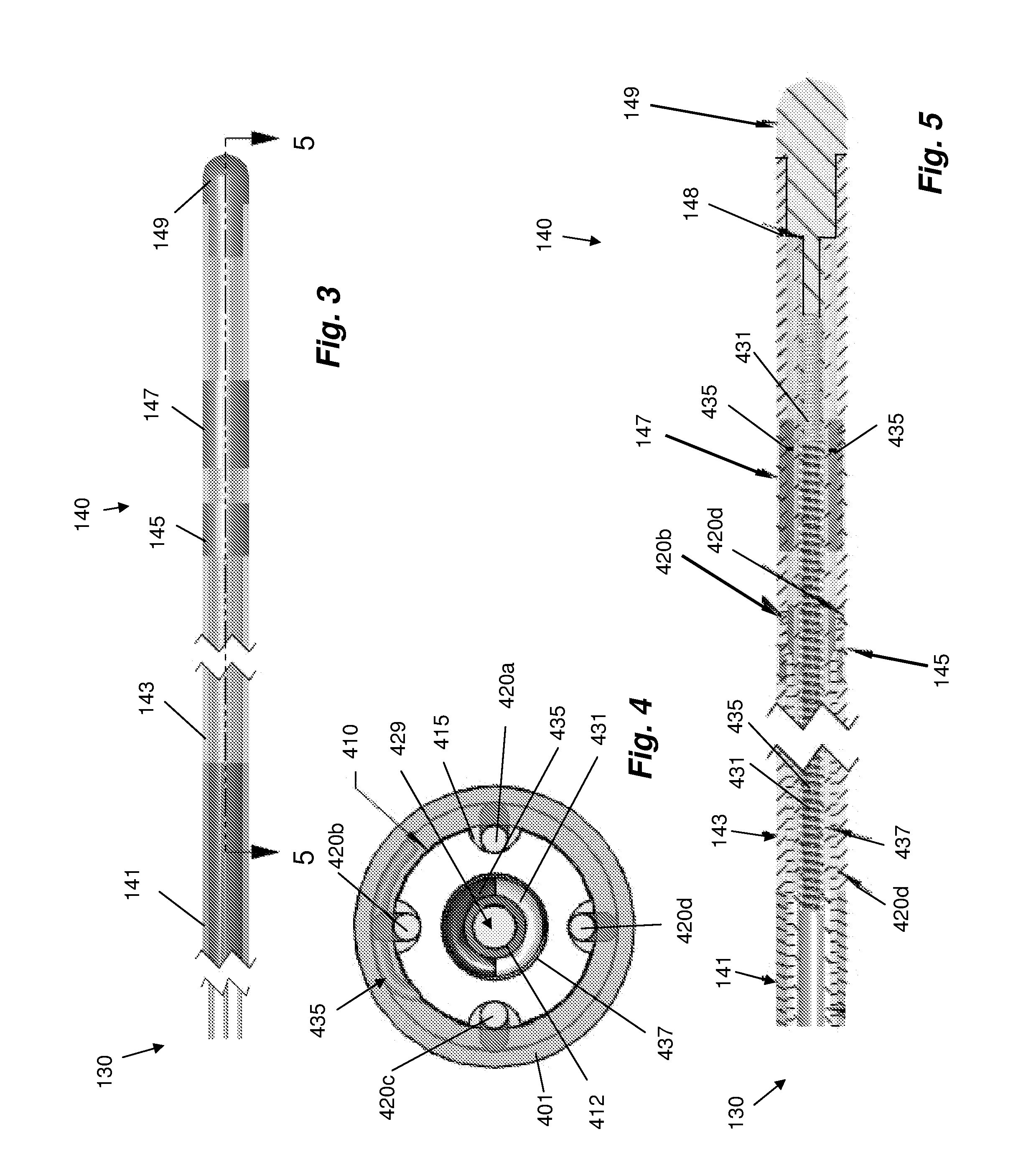
[0040]Referring to FIGS. 2 and 6, a control assembly 200, provided in the main handle 110 of the catheter lead assembly 100 includes at its proximal end, a swivel joint 280, embodied as a spherical ball joint. The swivel joint 280 allows for multi-axis movement of the control handle 120, which in-turn manipulates steering wires 420a, 420b, 420c, 420d (See FIGS. 4-6). The swivel joint 280 is set off from a control body...


PUM


Abstract

A steerable multi-polar lead shaft assembly includes a core member extending longitudinally through the shaft assembly, a plurality electrically conductive elements disposed within the core member, a plurality of steering wires circumferentially distributed about the core member. A control mechanism for a steerable catheter, such as the steerable multi-polar lead assembly, includes a mounting portion adapted to engage a steerable shaft, a stem extending from the mounting portion, a swivel joint arranged at a proximal end of the stem, a control yoke rotatably mounted on the swivel joint, adapted to engage a plurality of steering wires of the steerable catheter, and a handle connected with the yoke, adapted for direct manipulation by a user.

Description

CROSS-REFERENCE TO RELATED APPLICATIONS[0001]This application claims the benefit of priority to U.S. Provisional Patent Application No. 61 / 178,409 filed May 14, 2009 and to U.S. Provisional Patent Application No. 61 / 107,227 filed Oct. 21, 2008. This application is also related to U.S. patent application Ser. No. 11 / 261,304, filed Oct. 28, 2005, published as U.S. Patent Application Publication Number 2006 / 0095107. Each of the aforementioned applications is incorporated herein by reference in its entirety. U.S. patent application Ser. No. 10 / 911,975, filed Aug. 5, 2004, published as U.S. Patent Application Publication Number 2005 / 0060013, and U.S. Pat. Nos. 6,978,185 and 7,158,837 are each also incorporated herein by reference in its entirety.FIELD OF THE INVENTION[0002]The present invention relates to surgical catheters and leads. Particularly, the present invention is directed to control mechanisms for surgical catheters and leads for use in cardiac procedures, such as cardiac pacin...

Claims


Application Information

Patent Timeline
Patent Type & Authority Applications(United States)
IPC IPC(8): A61M25/00A61B18/18
CPCA61B5/0422A61M25/0147A61M25/0141A61M25/0136A61B5/287
Inventor OSYPKA, THOMAS P.SASS, TIMOTHY L.DELLY, ERIC W.DRUM, JEFF JEFFREY
Owner OSCOR
Learn More