
Negative Pressure, Thermal Energy Transfer Device That Also Provides Positive Pressure to the Patient

a technology of thermal energy transfer device and patient, applied in the field of negative pressure and thermal energy transfer unit, can solve the problem that patients do not receive the desired thermal energy transfer

Active Publication Date: 2010-04-29
STRYKER CORP
View PDF79 Cites 21 Cited by
  • Summary
  • Abstract
  • Description
  • Claims
  • Application Information

AI Technical Summary

Benefits of technology

[0025]A negative pressure, thermal energy device has an enclosure that receives a patient's hand or foot. The hand or foot is positioned in the enclosure and contacts a thermal energy contacting surface. The thermal energy contacting surface transfers its thermal energy to the patient. While in the enclosure, the hand and foot is also exposed to a negative pressure to cause vasodilation. The combination of the vasodilation and the thermal energy transfer, alters the patient's body core temperature. When the enclosure is just a non-shape altering material, the above-description is clearly disclosed in the prior art. A problem with the prior art is that if the patient moves its hand or foot from the thermal contacting surface, the patient does not receive the desired transfer of thermal energy. To ensure the patient's hand or foot remains in contact with the thermal contacting surface, the enclosure has portion thereof that is a shape altering material. When the negative pressure is applied to the shape altering material, the shape altering material is pulled toward the hand or foot to (a) provide a positive pressure on the hand or foot and (b) ensure the hand or foot effectively contacts the thermal energy contacting surface.

Problems solved by technology

A problem with the prior art is that if the patient moves its hand or foot from the thermal contacting surface, the patient does not receive the desired transfer of thermal energy.

Method used


Image

  • Negative Pressure, Thermal Energy Transfer Device That Also Provides Positive Pressure to the Patient
  • Negative Pressure, Thermal Energy Transfer Device That Also Provides Positive Pressure to the Patient
  • Negative Pressure, Thermal Energy Transfer Device That Also Provides Positive Pressure to the Patient

Examples


Embodiment Construction

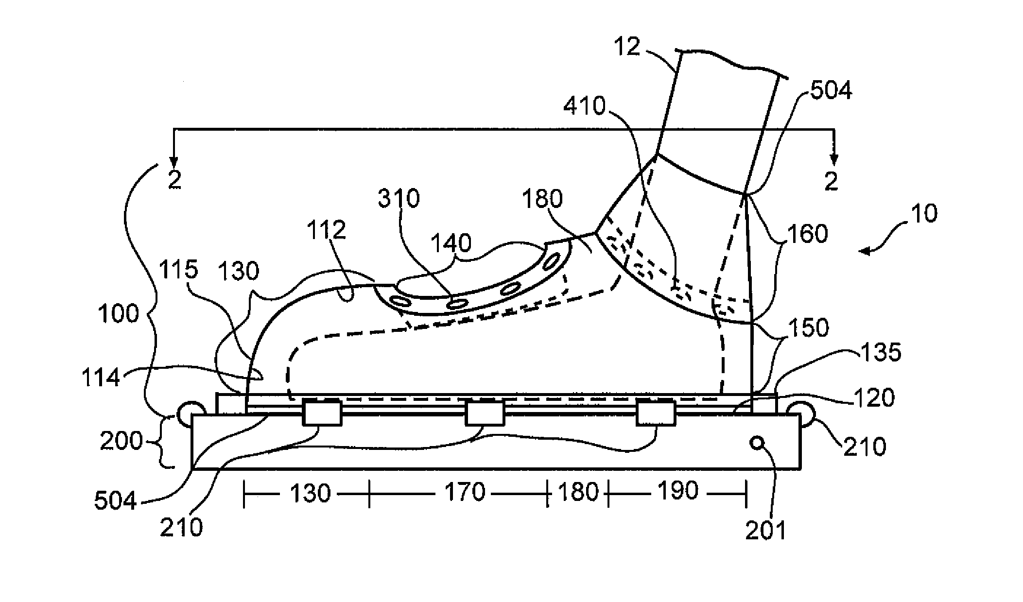
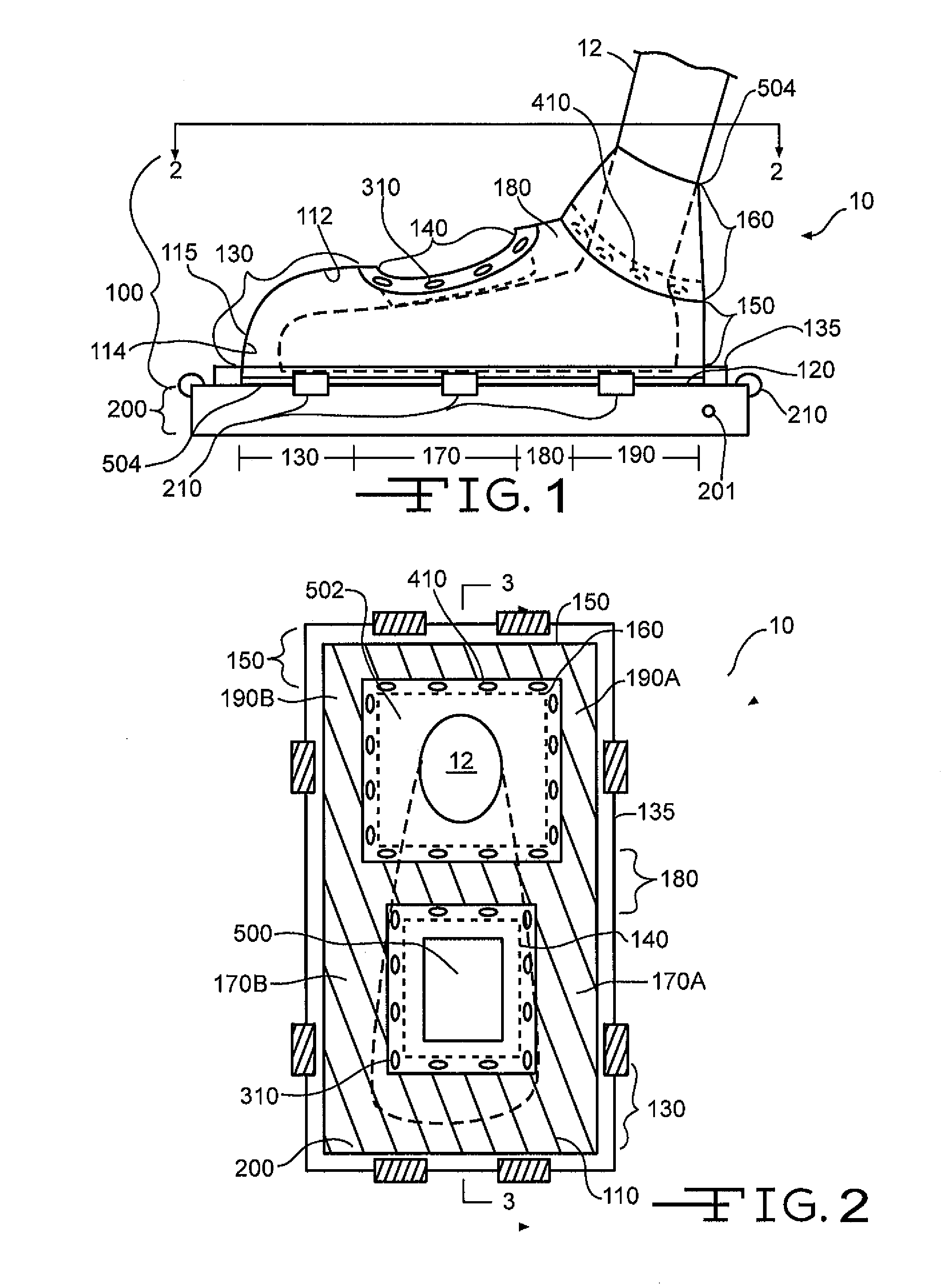
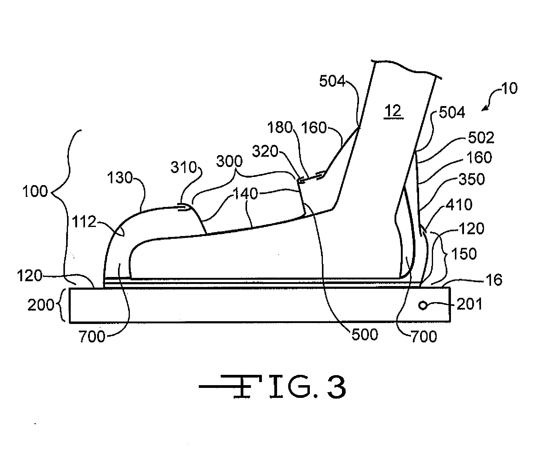
[0026]Turning to FIGS. 1, 2 and 3, the present invention is directed to a thermal-energy, negative pressure device 10. For ease of reference, we have incorporated a patient's foot, not claimed, in the thermal-energy, negative pressure device illustrated in FIGS. 1, 2 and 3. Obviously a patient's hand could have been illustrated as well. This thermal-energy, negative pressure device 10 can be divided into sections.

[0027]The sections include and are not limited to a contact section 100 and an operation section 200. As illustrated at FIG. 1, the contact section 100 has components that enclose the patient's foot. The operation section 200 has the components that (a) create the negative-pressure in the contact section 100, (b) generate or provide the desired thermal energy that the patient's foot experiences in the contact section 100, and (c) in one embodiment, contact the patient's foot.

Contact Section

[0028]The contact section 100 is further divided into a hard shell (a.k.a., a non-sha...


PUM


Abstract

A negative pressure, thermal energy device has an enclosure that receives a patient's body part. The body part is positioned in the enclosure and contacts a thermal energy contacting surface. The thermal energy contacting surface transfers its thermal energy to the body part. While in the enclosure, the body part is also exposed to a negative pressure to cause vasodilation. The combination of the vasodilation and the thermal energy transfer alter the patient's body core temperature. To ensure the body part remains in contact with the thermal contacting surface, the enclosure has a portion thereof that moves when negative pressure is in the enclosure. When the negative pressure is applied, the deforming enclosure material is pulled toward the body part to provide a positive pressure on the body part that ensures the body part effectively contacts the thermal energy contacting surface.

Description

FIELD OF THE INVENTION[0001]The present invention relates to negative pressure, thermal energy transfer units for controlling, maintaining and / or adjusting the body core temperature of a mammal, in particular a human.BACKGROUND OF THE INVENTION[0002]Stanford University is the assignee of U.S. Pat. Nos. 5,683,438; 6,602,277; 6,673,099; 6,656,208; 6,966,922; 7,122,047; and 6,974,442. These patents disclose a negative pressure, thermal energy device that can be applied to a patient. The negative pressure device has the following elements: (1) a hard, non-shape altering enclosure having an opening to receive a portion of a patient's body that contains a venous plexus area, (2) a vacuum system that creates a negative pressure in the enclosure, (3) a seal positioned at the enclosure's opening to maintain the negative pressure in the enclosure, and (4) a thermal energy system having a thermal energy contacting element wherein the venous plexus area is exposed to the thermal energy from the...

Claims


Application Information

Patent Timeline
Patent Type & Authority Applications(United States)
IPC IPC(8): A61F7/00
CPCA61F7/00A61F2007/0036A61H23/04A61F2007/0075A61H9/0057A61F2007/0045
Inventor BUCHANAN, RICHARDPEPE, GREGKEDGE, GERARD E.VAIL, MARCUS B.
Owner STRYKER CORP
Learn More