
Turbomachine flameout confirmation

a technology of turbine engines and flameout events, which is applied in the direction of machines/engines, mechanical equipment, sustainable transportation, etc., can solve the problems of non-combusted fuel being wastefully exhausted, difficult to detect a flameout event, and reduced pressure of compressed air supplied from external sources

Inactive Publication Date: 2010-05-06
HONEYWELL INT INC
View PDF19 Cites 6 Cited by
  • Summary
  • Abstract
  • Description
  • Claims
  • Application Information

AI Technical Summary

Benefits of technology

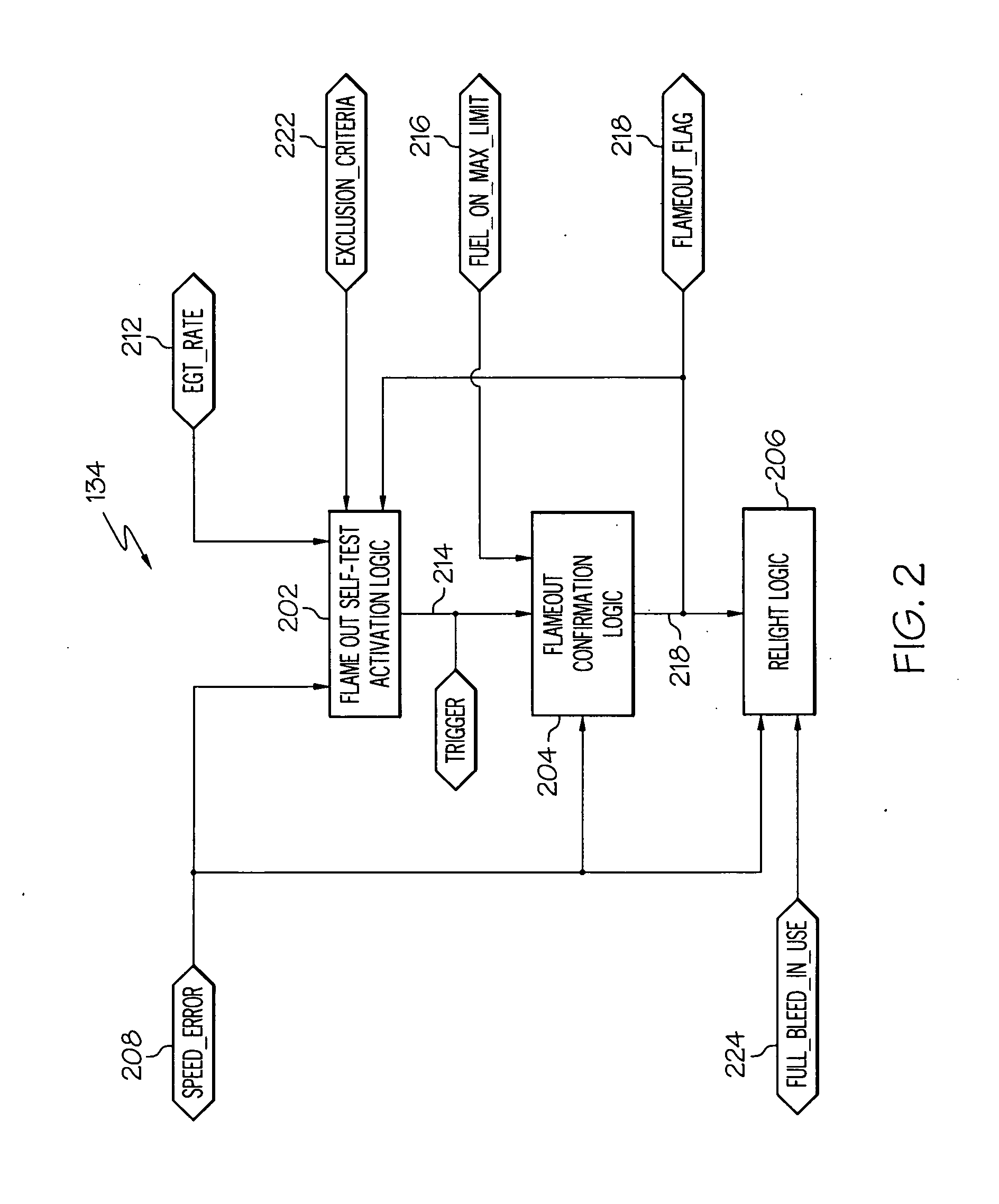
The patent describes a method and system for detecting flameout in a turbomachine that receives a controlled flow of bleed air and fuel. The system includes a speed sensor and temperature sensor to monitor the turbomachine's speed and temperature. The system uses logic to determine if there is a flameout based on the speed and temperature signals. The system can trigger a flameout confirmation test by holding the bleed air constant and increasing the turbomachine speed. The system can also confirm if flameout has occurred by detecting a maximum fuel flow limit and a speed error. The technical effect of this patent is to provide a reliable method for detecting flameout in a turbomachine and ensuring safe operation.

Problems solved by technology

While operating in the closed cycle mode, the compressed air that is supplied from the external source may decrease to an undesirably low pressure.
During burn and bleed mode operation of a turbomachine, it can be quite difficult to detect a flameout event.
If an undetected flameout occurs during bleed and burn operation, fuel will continue to be supplied to the turbomachine, resulting in non-combusted fuel being wastefully exhausted.

Method used


Image

  • Turbomachine flameout confirmation
  • Turbomachine flameout confirmation
  • Turbomachine flameout confirmation

Examples


Embodiment Construction

[0018]The following detailed description is merely exemplary in nature and is not intended to limit the invention or the application and uses of the invention. Furthermore, there is no intention to be bound by any theory presented in the preceding background or the following detailed description.

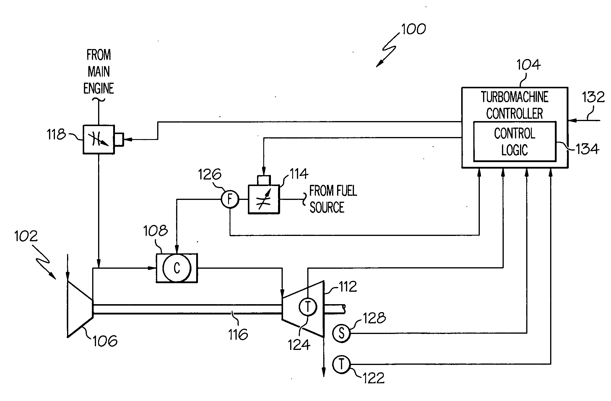
[0019]Referring now to FIG. 1, a schematic representation of an exemplary turbomachine control system 100 is depicted and includes a turbomachine 102 and a turbomachine controller 104. The turbomachine 102 includes a compressor 106, a combustor 108, and a turbine 112. When the turbomachine system 100 is configured to operate in its standard, open cycle mode, the compressor 106 draws in ambient air, compresses it, and directs the compressed air into the combustor 108. In the depicted embodiment, only a single compressor 106 is shown, though it will be appreciated that one or more additional compressors could be used.

[0020]In the combustor 108, the compressed air supplied from the compressor 1...


PUM


Abstract

Methods and apparatus are provided for detecting a flameout of an operating turbomachine that is configured to receive a controlled flow of bleed air from a bleed air source and a controlled flow of fuel from a fuel source. A value of an operational parameter within the turbomachine is detected and a determination is made as to whether it has varied by a predetermined amount. If the operational parameter has varied by the predetermined amount, a flameout confirmation test is triggered. The flameout confirmation test includes holding the controlled flow of bleed air constant, commanding an increase in turbomachine speed, and confirming that a flameout has occurred by detecting that the controlled fuel flow to the turbomachine is at a maximum fuel flow limit and that actual turbomachine speed differs from the commanded turbomachine speed by a predetermined speed error.

Description

STATEMENT REGARDING FEDERALLY SPONSORED RESEARCH OR DEVELOPMENT[0001]This invention was made with Government support under Contract No. N00019-02-C-3002, awarded by the U.S. Navy. The Government has certain rights in this invention.TECHNICAL FIELD[0002]The present invention generally relates to gas turbine engines and, more particularly, to a system and method for selectively confirming whether a flameout has occurred in a turbomachine.BACKGROUND[0003]Gas turbine engines, sometimes referred to as turbomachines, may be used in various environments to, among other things, generate electrical power, provide propulsion, supply compressed air for various pneumatic loads, and drive various mechanical loads. A typical gas turbine engine includes at least a compressor, a combustor, and a turbine. The compressor draws in ambient air, compresses the air, and supplies the compressed air to the combustor. The combustor receives the compressed air from the compressor, and a controlled flow of fu...

Claims


Application Information

Patent Timeline
Patent Type & Authority Applications(United States)
IPC IPC(8): F02C9/48
CPCF02C9/28F05D2270/08Y02T50/677F05D2270/092F05D2270/07Y02T50/60
Inventor CHRISTOPHER, MATTHEWVHORA, HANIF
Owner HONEYWELL INT INC
Learn More