Diagnostic apparatus

a diagnostic apparatus and diagnostic technology, applied in the field of diagnostic apparatus, can solve the problems of increasing complexity of the network, increasing the need for maintenance operations, and increasing the complexity of the network

Pending Publication Date: 2021-10-21
NIPPON TELEGRAPH & TELEPHONE CORP
View PDF7 Cites 1 Cited by
  • Summary
  • Abstract
  • Description
  • Claims
  • Application Information

AI Technical Summary

Benefits of technology

[0017]According to the present invention, a likelihood of whether an event obtained by a diagnosis using a probabilistic model is actually occurring at a diagnosis target can be confirmed.

Problems solved by technology

In communication networks, as virtualization and the like become more prevalent in order to provide various services, networks are becoming more and more complex and, accordingly, increasingly sophisticated maintenance operations are being required.
However, whether or not the fault estimated to be the fault cause is actually occurring is not comprehended and a separate confirmation operation is required when performing an actual fault response.

Method used


Image

  • Diagnostic apparatus
  • Diagnostic apparatus
  • Diagnostic apparatus

Examples


first embodiment

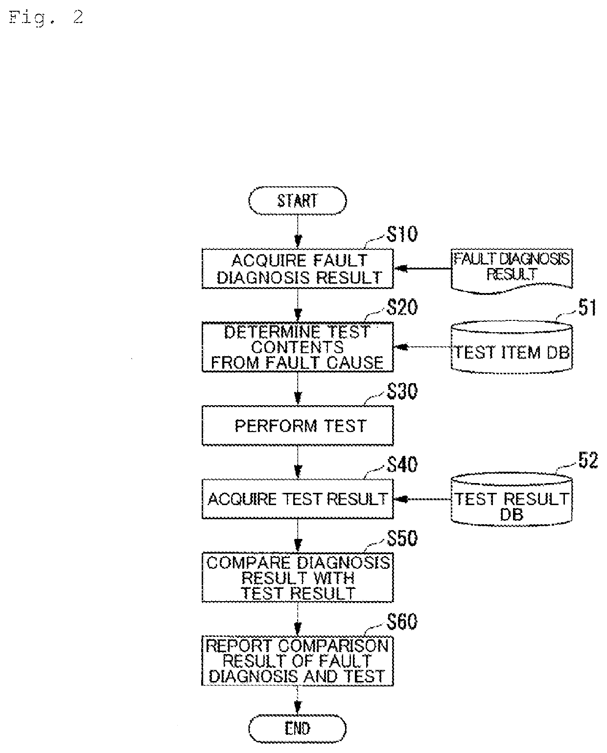
[0027]A first embodiment of the present invention will be described with reference to FIGS. 1 and 2.

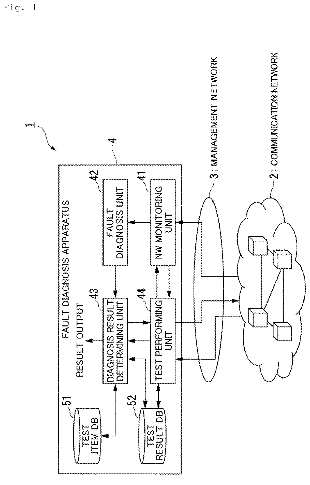
[0028]FIG. 1 is a configuration diagram of a fault diagnosis system 1 according to the present embodiment. The fault diagnosis system 1 includes a communication network 2, a management network 3, and a fault diagnosis apparatus 4. The fault diagnosis system 1 shown in FIG. 1 is an example in which a representative functional configuration of the present embodiment is adapted to a fault diagnosis system according to conventional art shown in FIG. 7. The fault diagnosis system 1 is equipped with a test function that confirms an actual state in the communication network 2 in accordance with a result of a fault diagnosis having been performed with respect to the communication network 2 in a similar manner to a fault diagnosis system according to conventional art.

[0029]The communication network 2 is, for example, a network constituted by a plurality of communication apparatuses. The manage...

second embodiment

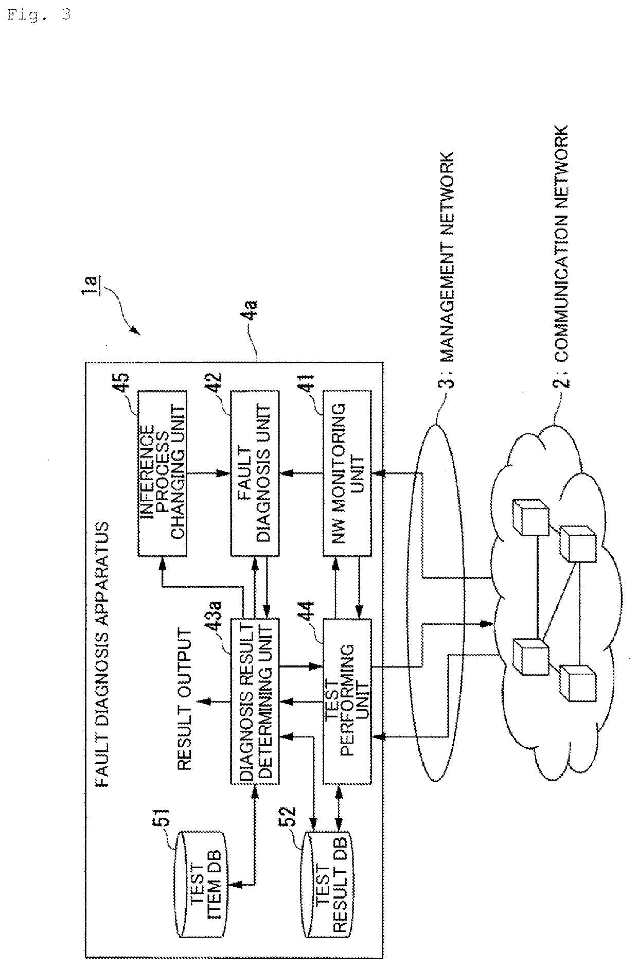
[0046]In the first embodiment, a diagnosis result of a fault diagnosis and a result of a confirmation test are compared with each other and a comparison result thereof and the diagnosis result are reported. In a second embodiment, when a difference occurs between a diagnosis result and a result of a confirmation test, a further fault diagnosis and a confirmation test are performed to improve accuracy of identifying a fault cause. The second embodiment will now be described with reference to FIGS. 3 and 4.

[0047]FIG. 3 is a diagram showing a configuration of a fault diagnosis system 1a according to the present embodiment. The fault diagnosis system 1a shown in FIG. 3 is an example in which a functional configuration that enables the fault diagnosis system according to conventional art shown in FIG. 7 to perform a re-execution of a fault diagnosis when a difference occurs in state estimation after performing a confirmation test and a change to an inference process used by the fault dia...

third embodiment

[0064]The fault diagnosis system 1 according to the first embodiment shown in FIG. 1 and the fault diagnosis system 1a according to the second embodiment shown in FIG. 3 adopt a configuration that includes only one NW monitoring unit 41 and only one fault diagnosis unit 42. However, in an actual network operation, since a fault diagnosis must be performed from an enormous amount of monitoring information and, with an increase in the amount of information handled, problems such as an increase in computational resources and an increase in calculation time occur. The present embodiment solves such a problem of scalability.

[0065]FIG. 6 is a diagram showing a configuration example of a fault diagnosis system 100 according to the present embodiment. In FIG. 6, same portions as the fault diagnosis system 1 according to the first embodiment shown in FIG. 1 are denoted by same reference signs and descriptions thereof will be omitted. The fault diagnosis system 100 shown in FIG. 6 includes a ...


PUM


Abstract

A fault diagnosis unit (42) of a fault diagnosis apparatus (4) performs a fault diagnosis of a communication network (2) with a probabilistic inference algorithm using information on the communication network (2) having been gathered by an NW monitoring unit (41). A diagnosis result determining unit (43) determines test items for confirming and determining a diagnosis result of the fault diagnosis. A test performing unit (44) performs a confirmation test of the determined test items. The diagnosis result determining unit (43) determines a likelihood of the diagnosis result of the fault diagnosis based on a result of the confirmation test.

Description

TECHNICAL FIELD[0001]The present invention relates to a diagnostic apparatus.BACKGROUND ART[0002]In communication networks, as virtualization and the like become more prevalent in order to provide various services, networks are becoming more and more complex and, accordingly, increasingly sophisticated maintenance operations are being required. In particular, in the field of fault diagnosis, creating a probabilistic model from monitoring information and fault cases of a network and performing fault diagnosis are being considered.[0003]FIG. 7 is a diagram showing a conventional fault diagnosis system. An operations manager performs NW monitoring in which various kinds of information (alert information, counter information, transmission quality information, and the like) in a communication network are gathered via a management network and monitored. The fault diagnosis system executes a fault diagnosis process using the gathered information as input and diagnoses a presence or an abse...

Claims


Application Information

Patent Timeline
Patent Type & Authority Applications(United States)
IPC IPC(8): H04L12/24
CPCH04L41/0695H04L41/0686G06Q10/00G06F11/22G06N7/00G06N20/00H04L43/50H04L41/0631H04L41/0677H04L43/10G01R31/002G01R31/318566G06N7/01
Inventor ODA, TAKUYAKOBAYASHI, SHOKEIHIRANO, AKIRA
Owner NIPPON TELEGRAPH & TELEPHONE CORP
Why Eureka
Try Eureka