Pneumatic fender and mouth piece metal for pneumatic fender

a pneumatic fender and pneumatic fender technology, which is applied in the direction of functional valve types, bumpers, valve construction, etc., can solve the problems of inability to detach the safety valve, violent ejection of air from the cavity, and failure of the fender bladder, so as to achieve the effect of significantly enhancing maintainability and greatly reducing labor and time required for these operations

Active Publication Date: 2017-11-14
THE YOKOHAMA RUBBER CO LTD
View PDF16 Cites 0 Cited by
  • Summary
  • Abstract
  • Description
  • Claims
  • Application Information

AI Technical Summary

Benefits of technology

[0004]The present technology provides a pneumatic fender and a mouth piece metal for a pneumatic fender with significantly enhanced maintainability wherein a safety valve can be attached and detached and a confirmation test of the valve opening pressure of the safety valve can be performed on the pneumatic fender while in use, and the labor and time required for these operations are greatly reduced.
[0038]an open position fixing member that fixes the open / close valve at a position in which the through hole is open. The closed position fixing member and the open position fixing member are disposed outside of the receiving chamber at a position to a surface side of the mouth piece metal, thus when the open / close valve is fixed at a position in which the through hole is open by the open position fixing member, the cavity of the receiving chamber and the cavity of the fender bladder are connected. Fixing of the open position fixing member can be performed to the surface side of the mouth piece metal, i.e. outside of the fender bladder. In this state, the safety valve functions normally. This enables the safety valve to open, thus reducing the internal pressure of the cavity and preventing damage when the fender bladder is excessively compressed.
[0040]The mouth piece metal further includes the receiving chamber communication passage that connects the cavity of the receiving chamber and outside air and the receiving chamber open / close valve that opens and closes the receiving chamber communication passage. This configuration allows the safety valve to be isolated from the cavity of the fender bladder, thus allowing the receiving chamber open / close valve to be opened and the internal pressure of the cavity of the receiving chamber to be raised to the pressure threshold via the receiving chamber communication passage. In other words, a confirmation test of the valve opening pressure of the safety valve can be performed on the pneumatic fender while in use. In such a manner, according to the present technology, the safety valve can be detached and attached and a confirmation test of the value opening pressure can be performed on the pneumatic fender while in use. As such, the labor and time required for these operations can be greatly reduced, and maintainability can be significantly enhanced.

Problems solved by technology

If the fender bladder remains sealed when the fender is excessively compressed, the internal pressure in the cavity may increase beyond a preset pressure threshold and cause failure of the fender bladder.
However, the cavity of the fender bladder of such a pneumatic fender when in use is inflated to a predetermined internal pressure, and so detaching the safety valve from the mouth piece metal of the fender bladder when the pneumatic fender is in use would result in air being violently ejected from the cavity.
Thus, such detachment of the safety valve is not possible.
Accordingly, the maintenance of detaching and attaching the safety valve to the mouth piece metal requires a great deal of man-hours and time.

Method used


Image

  • Pneumatic fender and mouth piece metal for pneumatic fender
  • Pneumatic fender and mouth piece metal for pneumatic fender
  • Pneumatic fender and mouth piece metal for pneumatic fender

Examples


Embodiment Construction

[0049]Hereinafter, a pneumatic fender and a mouth piece metal for a pneumatic fender of the present technology will be described with reference to embodiments illustrated in the drawings.

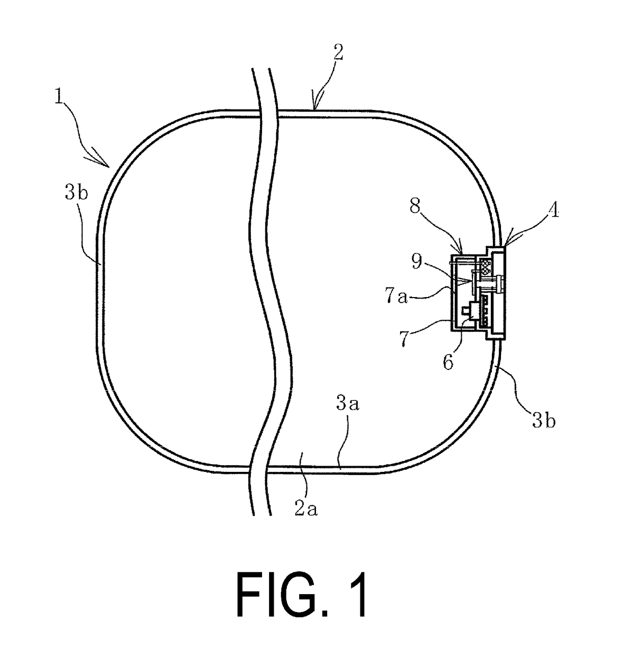
[0050]A pneumatic fender 1 (hereinafter, also fender 1) of the present technology illustrated in FIG. 1 to FIG. 5 includes a fender bladder 2 that is made mainly of rubber and has reinforcing material embedded therein. The fender bladder 2 is formed with a cylindrical portion 3a and a bowl-like hemispherical portion 3b on each end of the cylindrical portion 3a in the cylinder axial direction connected thereto.

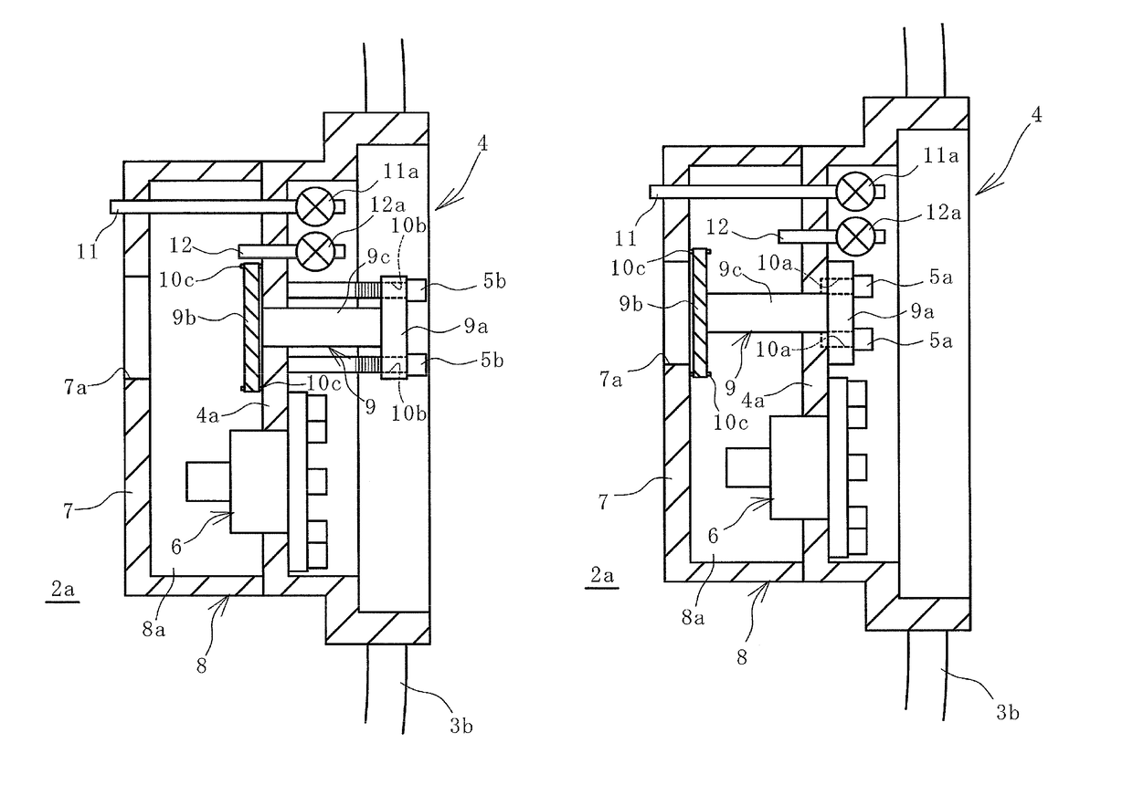
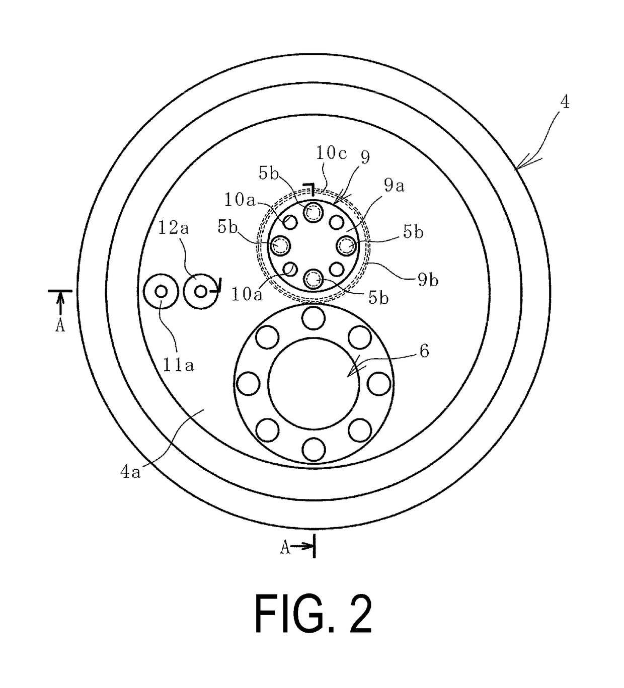
[0051]A mouth piece metal 4 of the present technology is provided on one of the hemispherical portions 3b. The mouth piece metal 4 may also be provided on the hemispherical portion 3b on both sides. The mouth piece metal 4 is a recessed cylinder-like fitting. The opening of the mouth piece metal 4 to the surface side may be covered by a lid attached by a bolt or the like.

[0052]The mouth piece m...


PUM


Abstract

A pneumatic fender and a mouth piece metal for a pneumatic fender with an open / close valve fixed at a position in which a through hole formed in a dividing wall constituting a receiving chamber, where the valve is closed by closed position fixing members. A safety valve is isolated from a cavity of a fender bladder by a receiving chamber, the safety valve being able to be detached and attached while the pneumatic fender is in use. A confirmation test of a valve opening pressure of the safety valve is performed by opening a receiving chamber open / close valve and raising an internal pressure of a cavity of the receiving chamber to a pressure threshold via a receiving chamber communication passage. The open / close valve is fixed at a position in which the through hole is open by open position fixing member.

Description

TECHNICAL FIELD[0001]The present technology relates to a pneumatic fender and a mouth piece metal for a pneumatic fender, and further relates to a pneumatic fender and a mouth piece metal for a pneumatic fender with significantly enhanced maintainability wherein a safety valve can be detached and attached and a confirmation test of the valve opening pressure of the safety valve can be performed on the pneumatic fender while in use, and the labor and time required for these operations are greatly reduced.BACKGROUND ART[0002]Pneumatic fenders are designed to have air sealed in the cavity of a fender bladder so as to be provided with predetermined performance such as shock absorbing performance. If the fender bladder remains sealed when the fender is excessively compressed, the internal pressure in the cavity may increase beyond a preset pressure threshold and cause failure of the fender bladder. To combat this, a safety valve that connects the cavity to the outside air may be provided...

Claims


Application Information

Patent Timeline
Patent Type & Authority Patents(United States)
IPC IPC(8): B60R19/20B63B59/02F16K17/02E02B3/26F16K1/00
CPCE02B3/26B63B59/02F16K17/02F16K1/00B63B2059/025F16K17/044F16K17/048Y02A30/30
Inventor YAMADA, SHU
Owner THE YOKOHAMA RUBBER CO LTD
Why Eureka
Try Eureka