Engine control experimenting apparatus

a technology of engine control and experimentation apparatus, which is applied in the direction of process and machine control, instruments, analogue processes for specific applications, etc., can solve the problems of long extreme difficulty in response of engines, and long time-consuming to carry out performance tests. , to achieve the effect of reducing the development cycle of engine control parts

Inactive Publication Date: 2012-09-25
NIKKI CO LTD
View PDF4 Cites 1 Cited by
  • Summary
  • Abstract
  • Description
  • Claims
  • Application Information

AI Technical Summary

Benefits of technology

[0009]The present invention was made to solve the problems as described above, and it is an object thereof to provide an engine control experimenting apparatus which makes it possible to control a fuel injection amount depending on an engine intake air flow rate or a rotating number of an engine, and makes it possible to easily perform a confirmation test of operation in all operation states with respect to the performance of various engine control parts to be used for constituting an engine system, thereby significantly reducing a development cycle of these engine control parts.

Problems solved by technology

Accordingly, when an experiment of each of the engine control parts is practically performed with a real engine system, it often takes a long time to carry out the performance test due to an interaction thereof and so on with the remaining engine control parts.
As a result, there occurs such a problem that a development cycle of every engine control part must have been prolonged.
Particularly, confirmation of responsiveness or the like at the time of change in the load or during the transient response of the engine must have encountered an extreme difficulty.
Nevertheless, even in a case where this testing toll is employed, it is still difficult to test the performance of the respective engine control parts in all operation states of the engine.
Particularly, since the simulation tool is obtained merely by reproducing, on a desk, the same conditions as those when being mounted on an actual system, it is not easy to check both hardware and software which include control performance, such as the responsiveness of an electronic control unit in various operation states of the engine.

Method used


Image

  • Engine control experimenting apparatus
  • Engine control experimenting apparatus
  • Engine control experimenting apparatus

Examples


Embodiment Construction

[0017]Hereinafter, the best mode for carrying out the present invention will be described with reference to the accompany drawing.

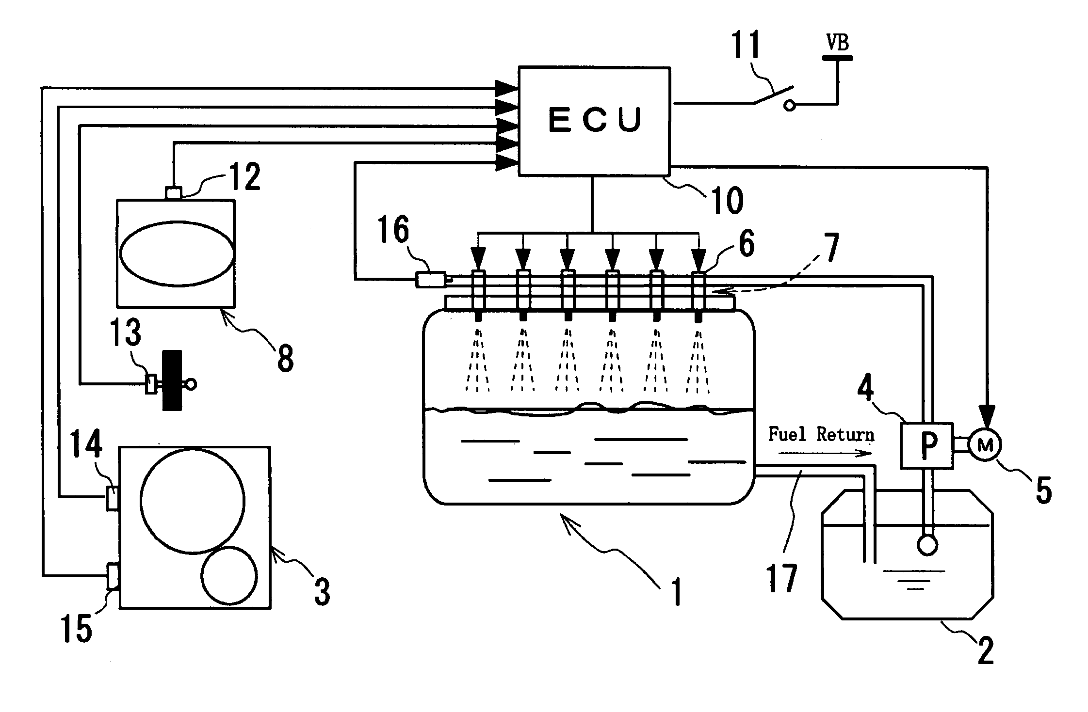
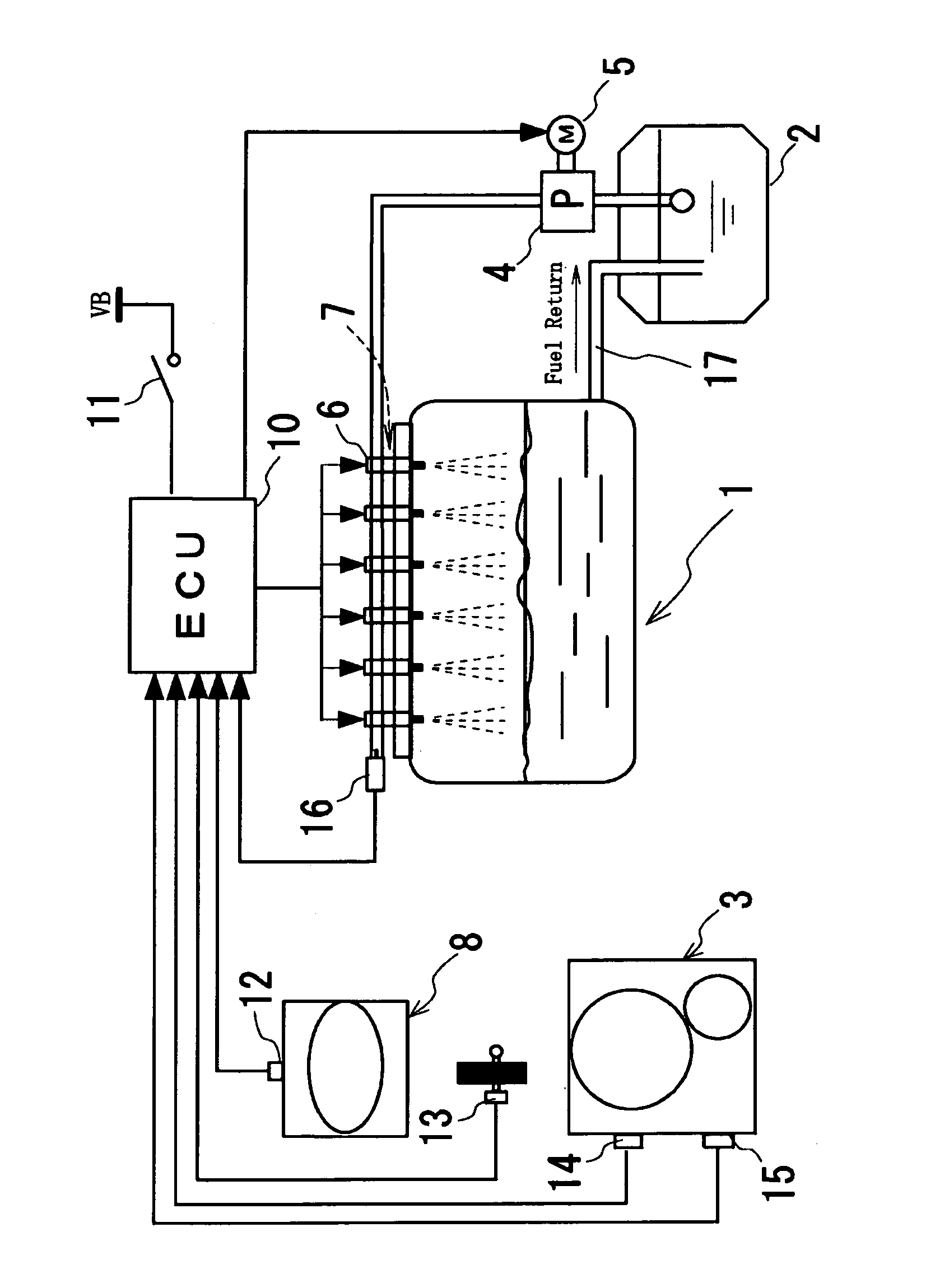
[0018]FIG. 1 is a block diagram illustrating a layout of an experimenting apparatus of various engine control parts according to the present invention. In a model engine 1, various engine control parts are constructed in a state where electrical transmission of signals and so on and fuel supply can be achieved in a manner substantially similar to a case where they are mounted on an actual engine. Specifically, an ignition device 7 which has a plurality of ignition plugs and a plurality of injectors 6 are mounted on the model engine, and fuel piping which extends from a fuel tank 2 and has a fuel pump 4 disposed on the midway is connected to the respective injectors 6. Additionally, an electronic control unit (ECU) 10 that is a fuel injection controller is adapted to further control driving of the injectors 6 and a motor 5 of the fuel pump 4 and to control...


PUM


Abstract

The invention aims at providing an engine control experimenting apparatus which enables to easily carry out a confirmation test of an operation in all operation states with regard to the performance of various engine control parts constituting an engine system. In this engine control experimenting apparatus, various engine control parts, which are actually mounted on an engine and are required for engine control, are constructed in a state where electrical transmission and fuel supply are enabled in a manner similar to a case where the engine control parts are mounted on a real engine, and a model-based control is performed on the same conditions as those of the actual engine, on the basis of experimental data of the real engine written in an electronic control unit constituting each of the engine control parts.

Description

BACKGROUND OF THE INVENTION[0001]1. Field of the Invention[0002]The present invention relates to an engine control experimenting apparatus which is able to test the performance of various control parts constituting a control system of an engine in various operation states when the control parts are practically mounted on the engine.[0003]2. Description of the Related Art[0004]Hitherto now, when the air-fuel ratio of an electronic engine is controlled, either maps or feedback control has been used. Instead of this, a model-based control has been recently put into practice as disclosed in, for example, Japanese Patent Application Laid-Open No. 10-27008.[0005]Meanwhile, since various engine control parts, such as actuators intended to be newly developed for being mounted on an engine, are not necessarily concurrent in the timings of development with each other, it is quite usual to individually conduct the performance test of the respective engine control parts with every engine contro...

Claims


Application Information

Patent Timeline
Patent Type & Authority Patents(United States)
IPC IPC(8): G01M15/00
CPCG05B17/02
Inventor SAWUT, UMERUJANYAMAGUCHI, SHINYATAKIGAWA, BUSO
Owner NIKKI CO LTD
Why Eureka
Try Eureka