Waste heat engine

a heat engine and waste technology, applied in the field of steam engines, can solve the problems of reducing engine efficiency of all types of engines, affecting the efficiency of engines, so as to achieve the effect of increasing or decreasing the size and outpu

Inactive Publication Date: 2010-05-06
CYCLONE POWER TECH
View PDF4 Cites 19 Cited by
  • Summary
  • Abstract
  • Description
  • Claims
  • Application Information

AI Technical Summary

Benefits of technology

[0005]Considering the foregoing, it is a primary object of the present invention to provide a steam engine that operates on low pressure, low temperature steam with the use of waste heat from an external heat source, such as an internal combustion engine, a refuse (e.g. garbage) burner, or a solar heat collector.
[0006]If is a further object of the present invention to provide a steam engine that operates on waste heat from an external heat source, and wherein the engine is self-starting.
[0007]It is still a further object of the present invention to provide a steam engine having a radial piston configuration, and wherein the engine operates on low pressure, low temper

Problems solved by technology

The need to operate at higher temperatures and pressures results in considerable heat loss in conventional steam engines.
And, while steam engines are typically larger in size and less efficie

Method used


Image

  • Waste heat engine
  • Waste heat engine
  • Waste heat engine

Examples


Embodiment Construction

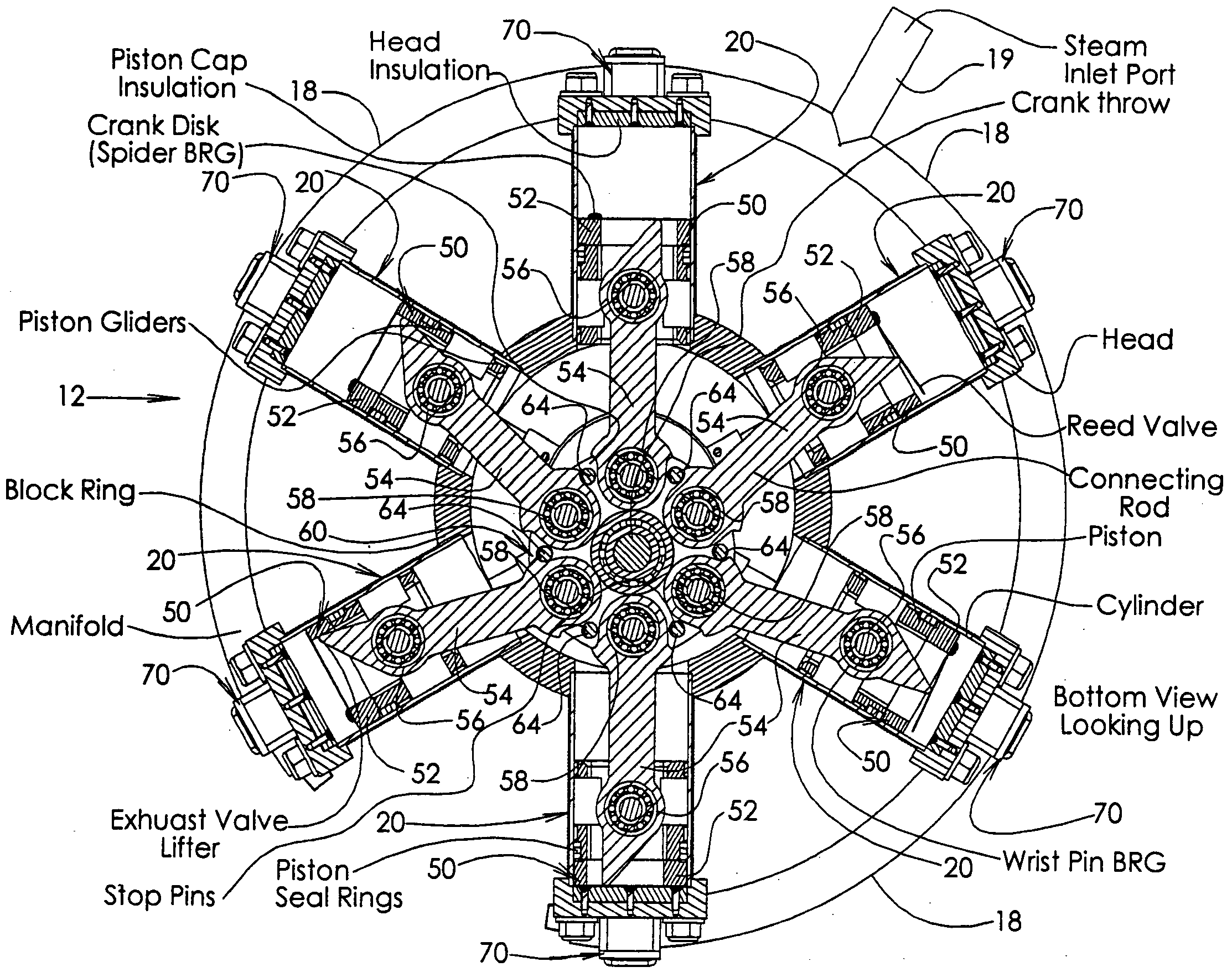
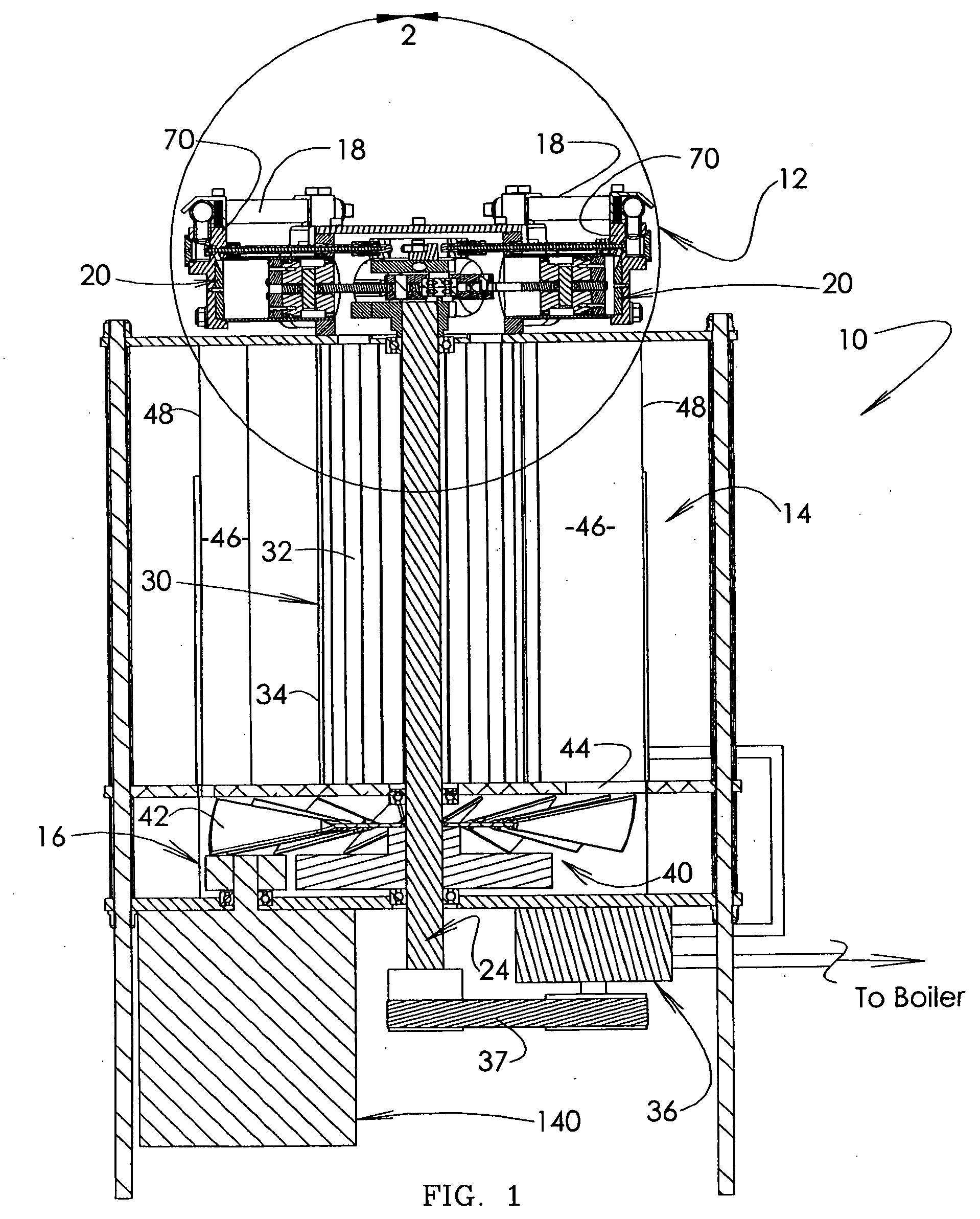
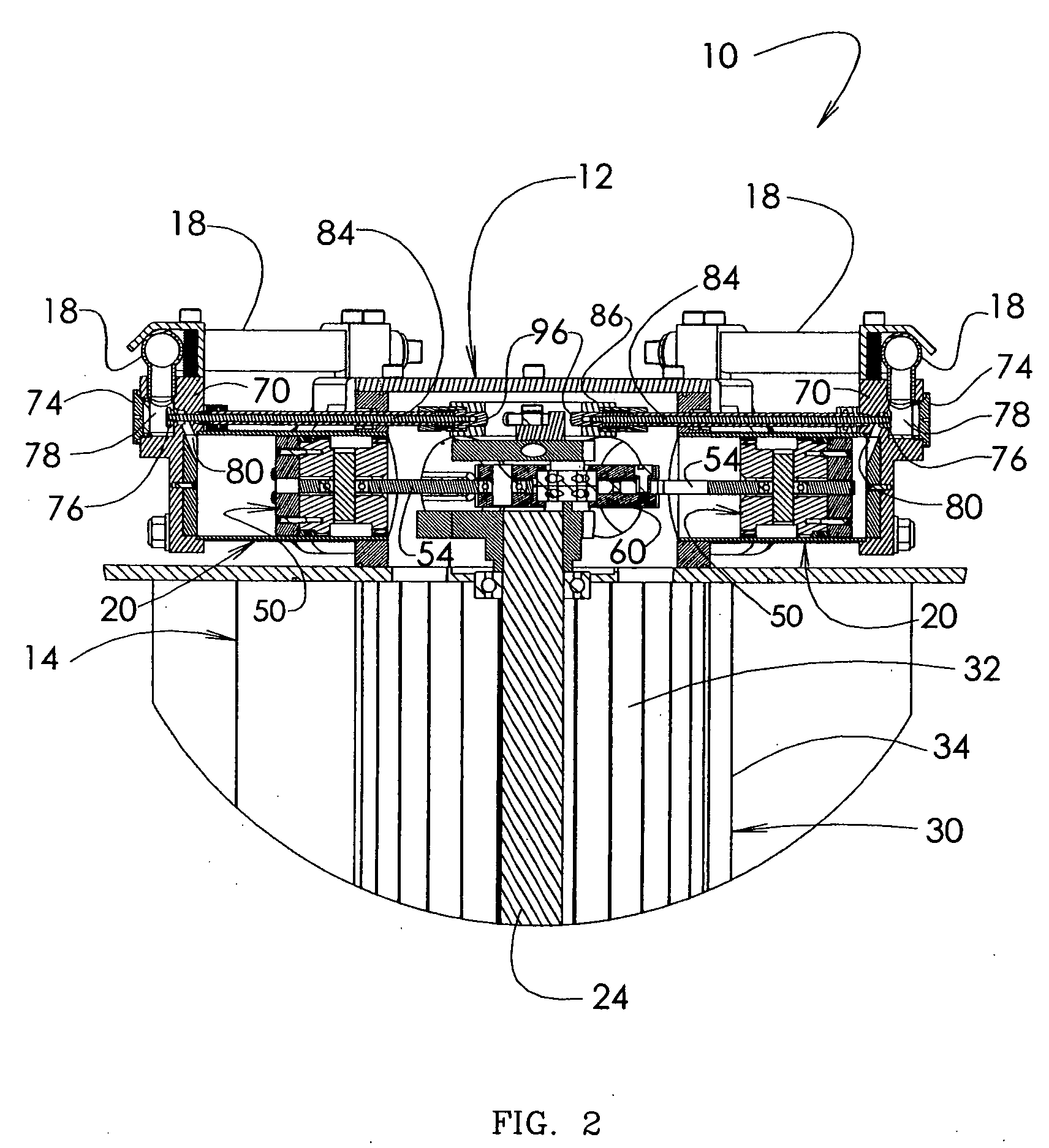
[0026]Referring to the several views of the drawings, and initially FIGS. 1-3, the waste heat engine of the present invention is shown and is generally indicated as 10. An upper portion 12 of the engine 10 has a radial arrangement of cylinders 20. Low pressure (i.e., generally between 20 psi-200 psi), low temperature (i.e., generally between 225° F. to 600° F.) steam is generated using waste heat from an external heat source (not shown) such as an internal combustion engine, a refuse (e.g., garbage, waste material) burner, or a solar heat collector to generate seam. Water from a condenser 30 is heated in an external boiler (not shown), using the waste heat to produce steam. The low pressure, low temperature steam is directed through a main line (not shown) that connects to a steam inlet port 19 on a generally circular manifold 18 that is supported on the upper portion 12 of the engine 10. Manifold 18 is structured and disposed to equally distribute the low pressure to intake valves ...


PUM


Abstract

An engine includes a radial arrangement of cylinders each having a reciprocating piston with a piston head and a connecting rod pivotally linked to the piston head at an upper end. A lower end of each connecting rod is pivotally linked to a crank disk that is rotatably mounted on a crank arm of a crankshaft. Steam intake valves at each cylinder are momentarily opened by a bearing cam roller that is moved in a circular path by rotation of the crank disk to sequentially engage spring urged cam followers on inboard ends of radially extending valve stems. Low pressure steam or gas is injected into the top of each cylinder, as the intake valves of the cylinders are opened in sequence, thereby forcing the piston in each cylinder through a power stroke to move the crank disk and turn the crankshaft. Angular displacement of each connecting rod through the return stroke of the piston urges an exhaust reed valve on the piston head to an open position, thereby releasing exhaust steam to a condenser chamber. The engine is self-starting and operates in a low pressure, low temperature range, using waste heat from an external source, such as exhaust from an internal combustion engine, burning of refuse (e.g. garbage or other solid waste material) or solar heat.

Description

BACKGROUND OF THE INVENTION[0001]1. Field of the Invention[0002]This invention relates to steam engines and, more particularly, to a low pressure, low temperature self-starting steam engine that uses waste heat from an external source, and wherein the engine includes a radial arrangement of cylinders with reciprocating pistons for driving rotation of a crankshaft.[0003]2. Discussion of the Related Art[0004]The need to operate at higher temperatures and pressures results in considerable heat loss in conventional steam engines. And, while steam engines are typically larger in size and less efficient than internal combustion engines and diesel engines, (unless operating at high temperatures and pressures) the loss of heat in all types of engines significantly reduces engine efficiency. Accordingly, the ability to harness heat loss during engine operation is highly beneficial and can improve overall engine efficiency. Moreover, waste heat from normal engine operation, as well as other h...

Claims


Application Information

Patent Timeline
IPC IPC(8): F01B29/12F01B1/06
CPCF01B17/04F01B1/062
Inventor SCHOELL, HARRY
Owner CYCLONE POWER TECH
Why Eureka
Try Eureka