Air cooling apparatus for a purge valve

Active Publication Date: 2010-05-06
GENERAL ELECTRIC CO
View PDF14 Cites 3 Cited by
  • Summary
  • Abstract
  • Description
  • Claims
  • Application Information

AI Technical Summary

Benefits of technology

[0006]In one exemplary, but non-limiting embodiment, the present invention relates to a cooling enclosure for a valve comprising an elongated housing body having a pair of housing portions and a pair of removable end plates, the pair of housing portions separable along at least one longitudinally-extending seam; means for securing the pair of housing portions engaged along the at least one longitudinal extending seam; one or more apertures for accommodating a like number of valve fittings; and cooling air inlet and outlet openings in the housing body for supplying and removing cooling air to the housing body.
[0007]In

Problems solved by technology

This air/oil interface on the coated surfaces of the piping system and valves (for example, check valves, ball valves, spool valves, purge valves, etc.) in the presence of the radiated, conducted and convected heat, leads to coke formation in

Method used


Image

  • Air cooling apparatus for a purge valve
  • Air cooling apparatus for a purge valve
  • Air cooling apparatus for a purge valve

Examples


Example

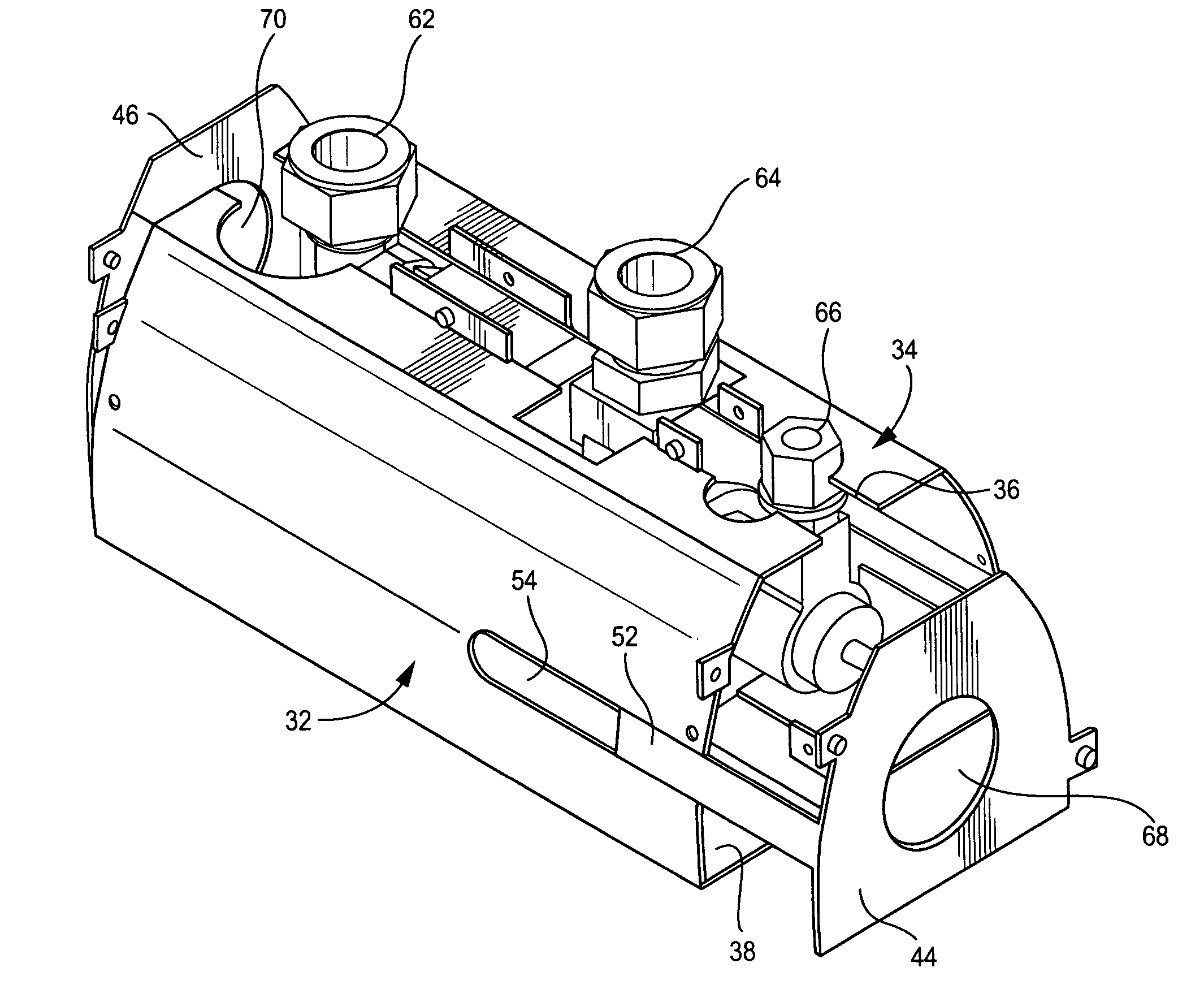
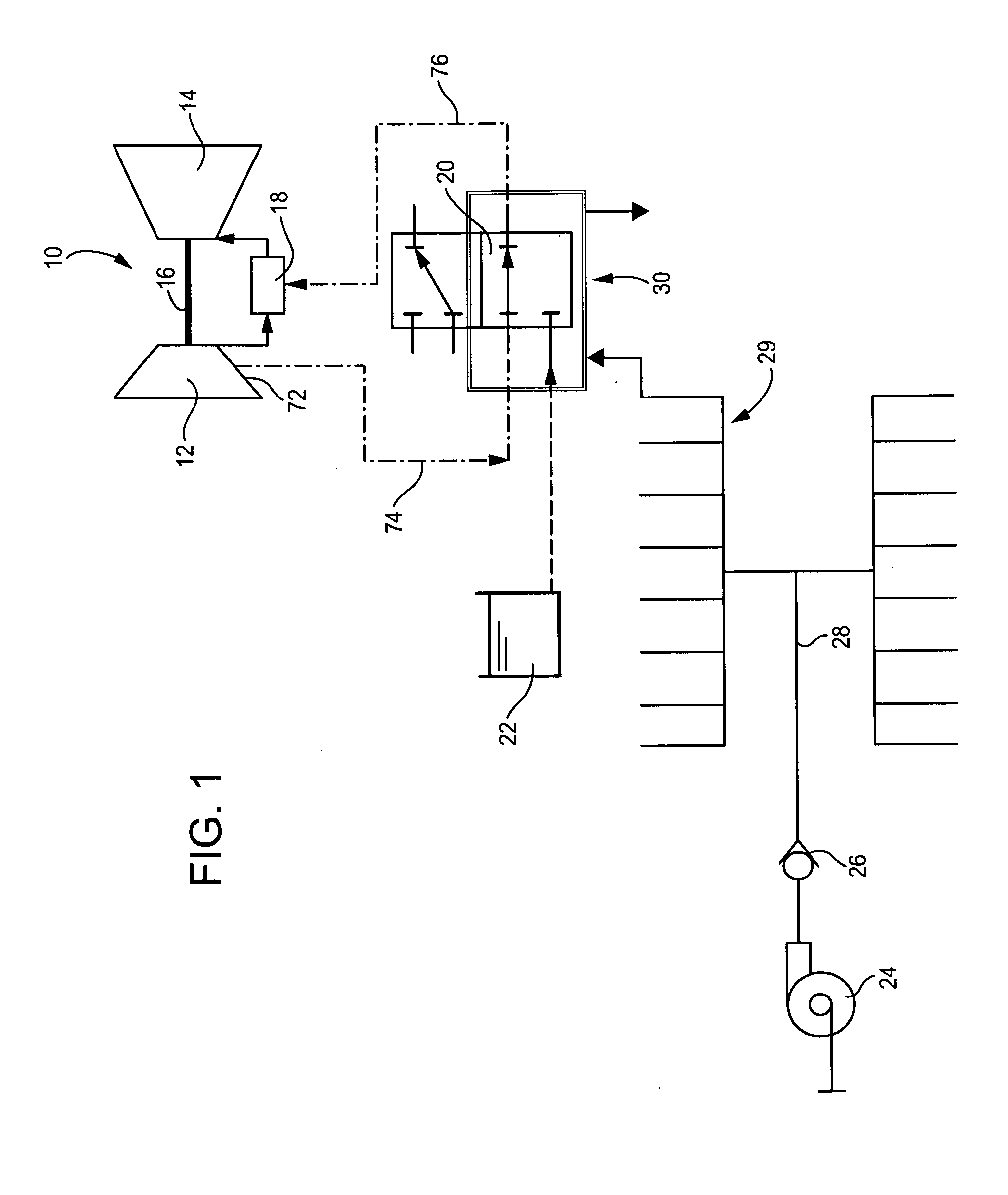
[0013]With reference initially to FIG. 1, a gas turbine 10 typically includes a compressor 12 and a turbine 14 mounted on a single shaft 16. A combustor 18 is arranged to burn a fuel air mixture and to supply the hot gaseous products of combustion to the turbine 14. A three-way purge valve 20 is arranged to supply either liquid or purge to the combustor 18. Liquid fuel is supplied to the purge valve from a liquid fuel source 22 while purge air is supplied to the valve 20 by means of a blower 24, a check valve 26, supply conduit 28 and a manifold 29. The purge air is used when liquid fuel is not flowing (for example, when natural gas fuel is being used) to keep the liquid fuel nozzles cool (and thus prevent coking) and to prevent backflow.

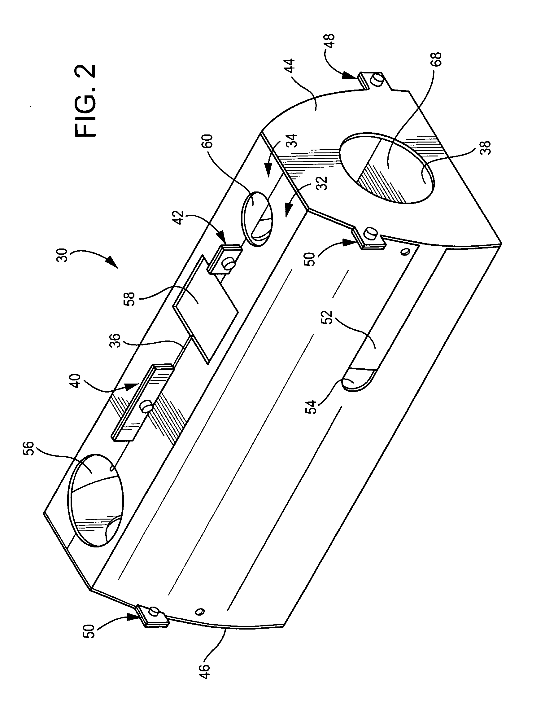
[0014]In the exemplary but nonlimiting embodiment described herein, the invention relates particularly to an apparatus for use in cooling the three-way purge valve 20. A cooling housing 30 is designed for easy installation about the purge valve 20. ...


PUM


Abstract

A cooling enclosure for a valve includes an elongated housing body having a pair of housing portions and a pair of removable end plates, the pair of housing portions separable along at least one longitudinally-extending seam. Fastener devices are provided for securing the pair of housing portions engaged along the at least one longitudinal extending seam. One or more apertures are provided for accommodating a like number of valve fittings, and cooling air inlet and outlet openings are also provided in the housing body for supplying and removing cooling air to the housing body.

Description

[0001]This invention relates to gas turbine technology generally, and to a system for cooling liquid fuel components subject to conduction and radiation heating, such as a three-way purge valve.BACKGROUND OF THE INVENTION[0002]Gas turbines typically operate on natural gas fuel, with fuel oil (typically no. 2 distillate) often used as a contingency for periods of gas unavailability. When a gas turbine is operating on natural gas fuel, the fuel oil typically remains in liquid fuel lines (for example, piping / tubing) leading to the combustor nozzles of the gas turbine. The stagnate fuel oil in a liquid fuel lines is often exposed to the turbine compartment air temperatures of up to 200° F., and turbine surfaces of up to 800° F.[0003]Typically, a gas turbine has a number of combustors positioned around the turbine, each combustor having a gas fuel nozzle and liquid fuel nozzle. When the turbine is running on one type of fuel, the nozzle for the other type of fuel must be purged of the ot...

Claims


Application Information

Patent Timeline
IPC IPC(8): F02C7/18F02C7/12F01D25/12F16K49/00
CPCF16K49/005Y10T137/7062Y10T137/6525
Inventor SMITH, DAVID W.BYRD, DOUGBLACK, MICHAEL P.TIWARI, SWAPNIL
Owner GENERAL ELECTRIC CO
Why Eureka
Try Eureka