V-belt drive with a force returning device

a technology of force return device and wedge drive, which is applied in the direction of presses, manufacturing tools, press rams, etc., can solve the problems of gas pressure springs of that kind that have a tendency to get hot and then possibly fail, etc., and achieve reliable and good line contact , avoid the risk of jamming of wedge drive, cost saving

Active Publication Date: 2010-05-06
WEIGELT HARALD
View PDF17 Cites 0 Cited by
  • Summary
  • Abstract
  • Description
  • Claims
  • Application Information

AI Technical Summary

Benefits of technology

[0026]It has further proven to be advantageous for the transverse wedge to be arranged between the first portion of the positive-action return device, that engages the slider element, and the slider element, as here it is possible to provide a fixing to the slider element. The arrangement is thus advantageously implemented between a shoulder of the positive-action return device, that engages the slider element in positively locking relationship, and a corresponding groove or recess in the slider element, into which the shoulder engages.
[0027]Advantageously the transverse wedge or the adjusting device is or can be fixed to the slider element. To permit adjustment, there can be provided in particular a slot, by way of which the adjusting device or the transverse wedge can be fixed to the slider element. Transverse displacement of the transverse wedge or the device provides that the positive-action retraction effect or the positive-action return device, after assembly of the slider element, can be easily adapted to the respective manufacturing dimension of the surface of the driver element as it engages the positive-action return device. Subsequently the positive-action return device is only still secured or fixed in the set position. It will be seen that in that way it is possible to achieve a considerable cost saving in comparison with the complicated post-working operation required in the state of the art. In addition that makes it possible to involve an operationally certain and reliable configuration in respect of the overall arrangement of the wedge drive and in particular the connection of its components of the slider element and the driver element.
[0028]It has further proven to be particularly advantageous if the at least one surface on the driver element has a rounded end region, over which the roller or the roller-like element can roll away without any problem in order to pass out of or into engagement with the surface of the driver element.
[0029]It has proven further to be advantageous if the at least one roller or the at least one roller-like element is of a diameter corresponding at least to double the radius of the rounded end region or a larger diameter than would correspond to half the width of the positive-action return device. Particularly preferably the roller or the roller-like element projects with its peripheral extent beyond the outer edge of the positive-action return device. By virtue of the provision of such a large roller, that permits on the one hand a particularly reliable and good line contact on the surface of the driver element for the roller or the roller-like element. On the other hand that permits a large force to be absorbed as the roller is sufficiently stable to carry or absorb even high pressing forces. Tilt-free rolling over the surface of the driver element can also be ensured, which results in avoiding the risk of jamming of the wedge drive even without or precisely without the provision of a gas pressure spring or another spring system.
[0030]It has proven to be further advantageous to provide at least one device for sliding guidance for carrying relatively high forces. In that case the actual retraction travel is not provided exclusively by way of the at least one roller or the at least one roller-like element, but a combination with a sliding guide means is provided for carrying relatively high forces. The at least one roller or the at least one roller-like element then serve in particular for minimizing wear when passing over the rounded end region as the entry or exit radius so that it is possible to achieve an even longer service life for the positive-action return device. The actual force in the advanced condition of the slider element of the wedge drive or the press, that is to say in the working position or in the lower dead center point of the press, can be carried primarily by way of the sliding guide means and not by way of the at least one roller or the at least one roller-like element, in which case the force which can be applied can also be markedly increased in relation to the provision of only the at least one roller or the at least one roller-like element, in which case they afford their particular advantage in respect of the retraction movement.

Problems solved by technology

Gas pressure springs of that kind have a tendency, in the event of prolonged actuation, to become hot and then possibly fail.
In the event of a failure, they lead, in the state of the art, to jamming of the wedge drive.
Shortly before they separate or slide away from each other, those surfaces which slide against each other, or that end region on the driver element, is subjected to a particularly high level of abrasive wear although the state of the art also provides that there is a rounding here on the sliding surface on the driver element.

Method used


Image

  • V-belt drive with a force returning device
  • V-belt drive with a force returning device
  • V-belt drive with a force returning device

Examples


Embodiment Construction

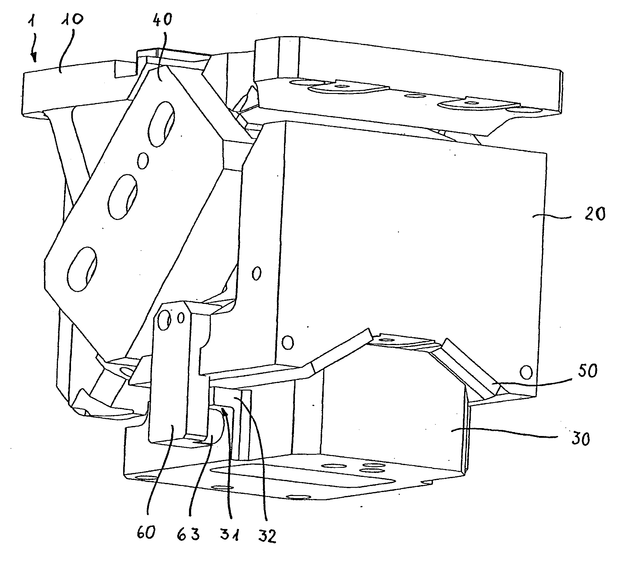
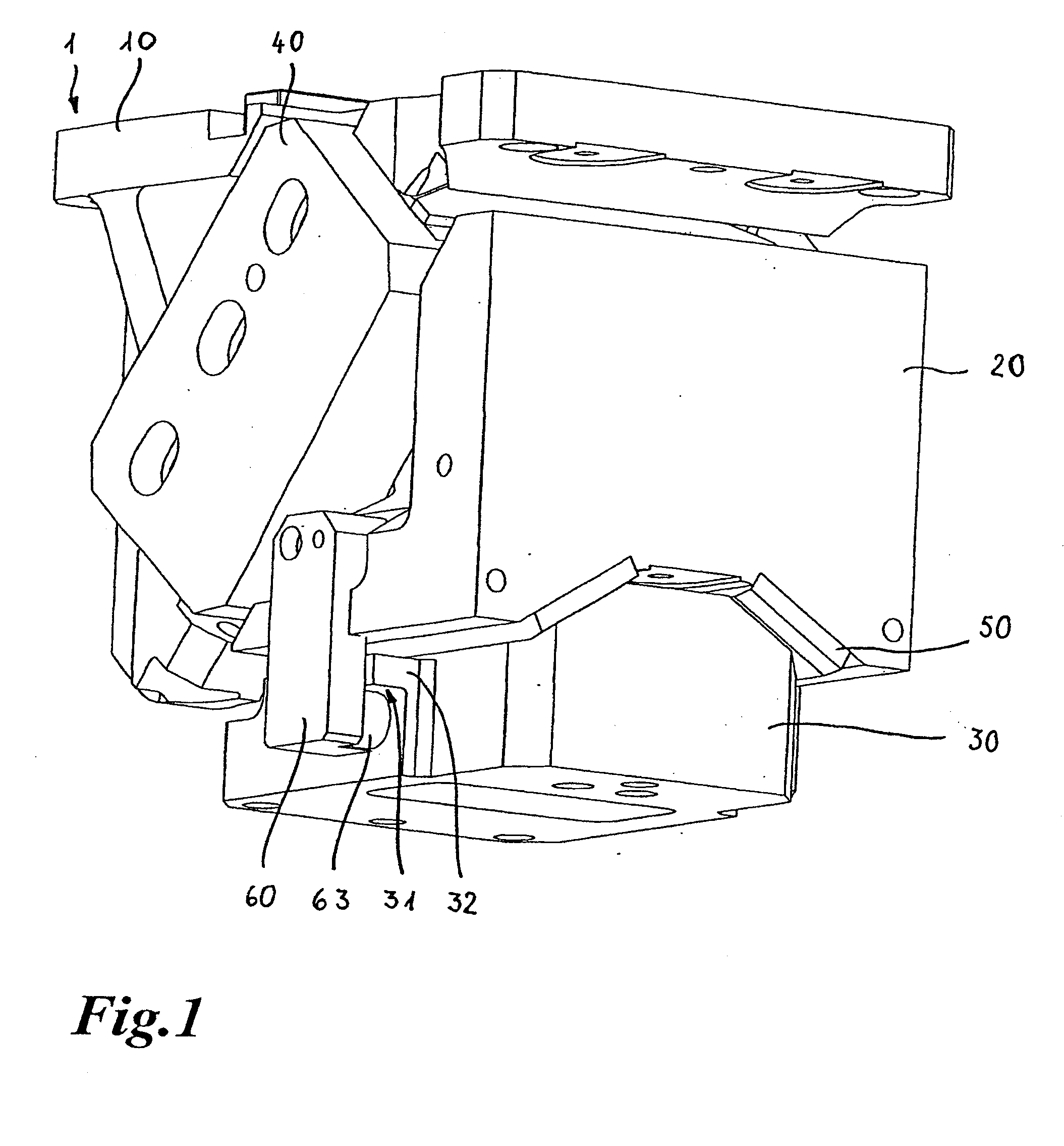
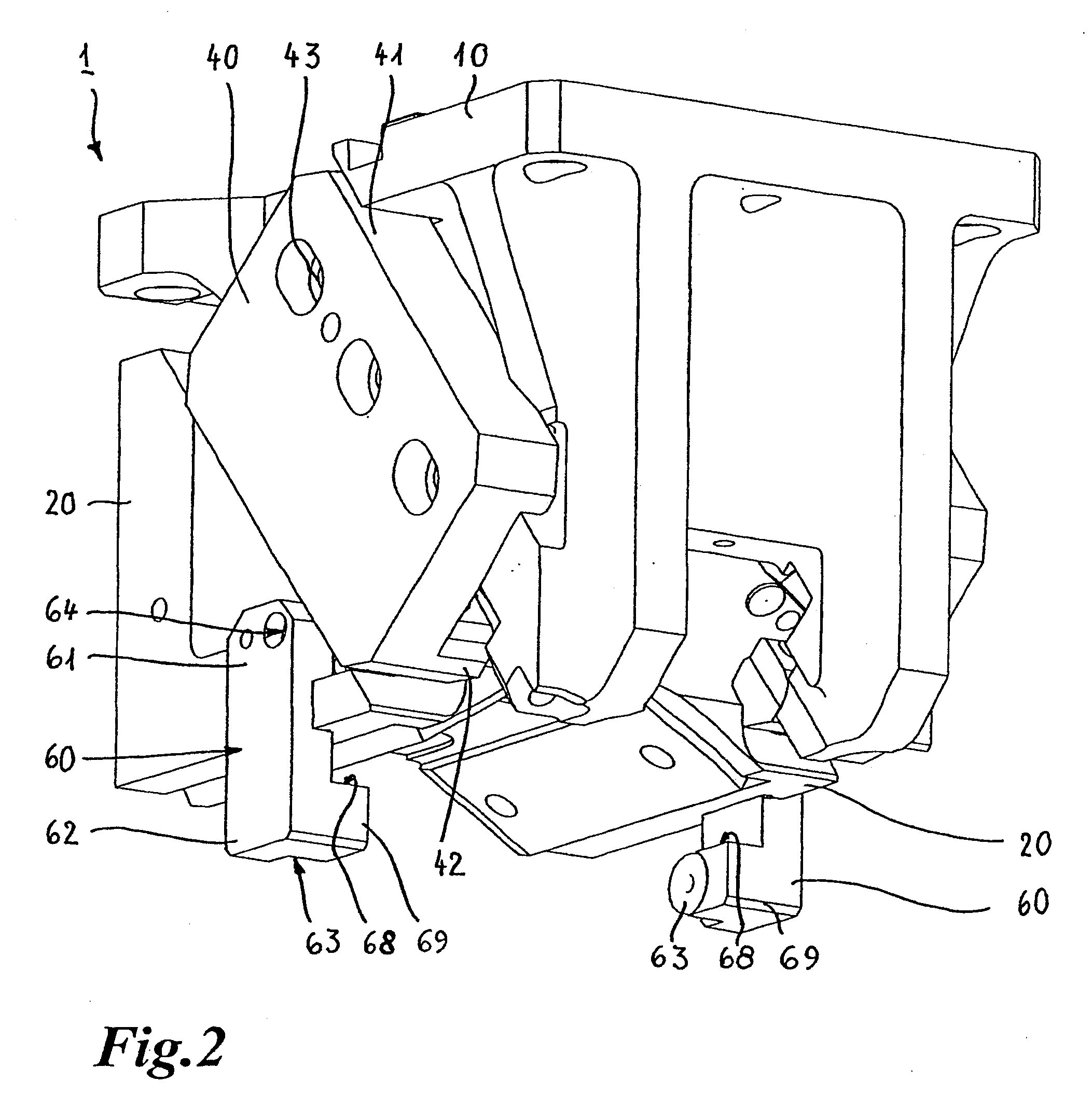
[0041]FIG. 1 shows a perspective view of an embodiment of a wedge drive 1 comprising a slider guide element 10, a slider element 20 and a driver element 30. The slider guide element 10 and the slider element 20 are connected together by way of two guide clamps 40. That structure corresponds to the structure described in WO 02 / 30659 A1. The guide clamps are respectively connected to the slider guide element and the slider element by way of holding projections 41, 42 engaging into corresponding grooves in the slider guide element and the slider element. The guide clamps are further connected to the slider guide element by way of screws 43 which are only indicated, as can be better seen from FIG. 2. The provision of the guide clamps means that the slider element and the slider guide element can be particularly well held together, in which case a required running clearance or play can be ensured even when the temperature of the wedge drive rises as the guide clamps can accommodate not o...


PUM

PropertyMeasurementUnit
working forceaaaaaaaaaa
displacementaaaaaaaaaa

Abstract

In a wedge drive (1) with a first part (20) which can be provided with a machining tool and a second part (30), wherein the two parts (20, 30) are arranged movably relative to each other, and there is provided at least one positive-action return device which engages or can engage both parts (20, 30), and a third part (10) which is connected to the first part (20), the at least one positive-action return device is return spring-free and has at least one device for causing and/or supporting the return of the one part (20) and/or for increasing the retraction force which can be applied in the return of the one part (20) in the upward stroke movement of the third part (10).

Description

BACKGROUND OF THE INVENTION[0001]1. Field of the Invention[0002]The invention concerns a wedge drive or cotter key with a first part which can be provided with a machining tool and a second part, wherein the two parts are arranged movably relative to each other, and there is provided at least one positive-action return device which engages or can engage both parts, and a third part which is connected to the first part.[0003]2. State of the Art[0004]Wedge drives are used in particular in the automobile industry for converting a perpendicular pressing force into a horizontal movement. In particular in the production of bodywork parts, it is possible in that way to carry out shaping processes or operations for cutting or perforating bodywork parts, which is not possible by means of a perpendicular working movement, that is to say the normal direction of movement of a press. Wedge drives must therefore be so designed that they convert very high working pressures of a press into the desi...

Claims


Application Information

Patent Timeline
Patent Type & Authority Applications(United States)
IPC IPC(8): B21D31/00
CPCB21D28/32B30B1/40
Inventor WEIGELT, HARALD
Owner WEIGELT HARALD
Why Eureka
Try Eureka