
Worktable of a table saw

a worktable and table saw technology, applied in the field of table saws, can solve the problems of increasing the wall thickness of the aluminum worktable relatively, increasing the consumption of aluminum, and heavy worktable weight, and achieves the effects of high structural strength, high working stability, and relatively reduced total weight of the worktabl

Inactive Publication Date: 2010-05-06
DURQ MACHINERY
View PDF6 Cites 5 Cited by
  • Summary
  • Abstract
  • Description
  • Claims
  • Application Information

AI Technical Summary

Benefits of technology

[0007]The present invention has been accomplished under the circumstances in view. It is the main object of the present invention to provide a worktable for table saw, which has high strength and low cost characteristics.
[0009]By means of the relatively smaller design of the reinforcing plate, the total weight of the worktable can be relatively reduced. Further, by means of reinforcing the main worktable plate with the reinforcing plate, the worktable has a high structural strength, assuring high working stability and operation safety of the table saw.

Problems solved by technology

However, in order to support the total weight of a cutting mechanism for table saw and to protect against deformation, an aluminum worktable for table saw must be made having a great wall thickness, resulting in a heavy weight of the worktable.
Further, increasing the wall thickness of an aluminum worktable relatively increases the consumption of aluminum.
In consequence, the cost of the worktable is relatively increased.

Method used


Image

  • Worktable of a table saw
  • Worktable of a table saw
  • Worktable of a table saw

Examples


Embodiment Construction

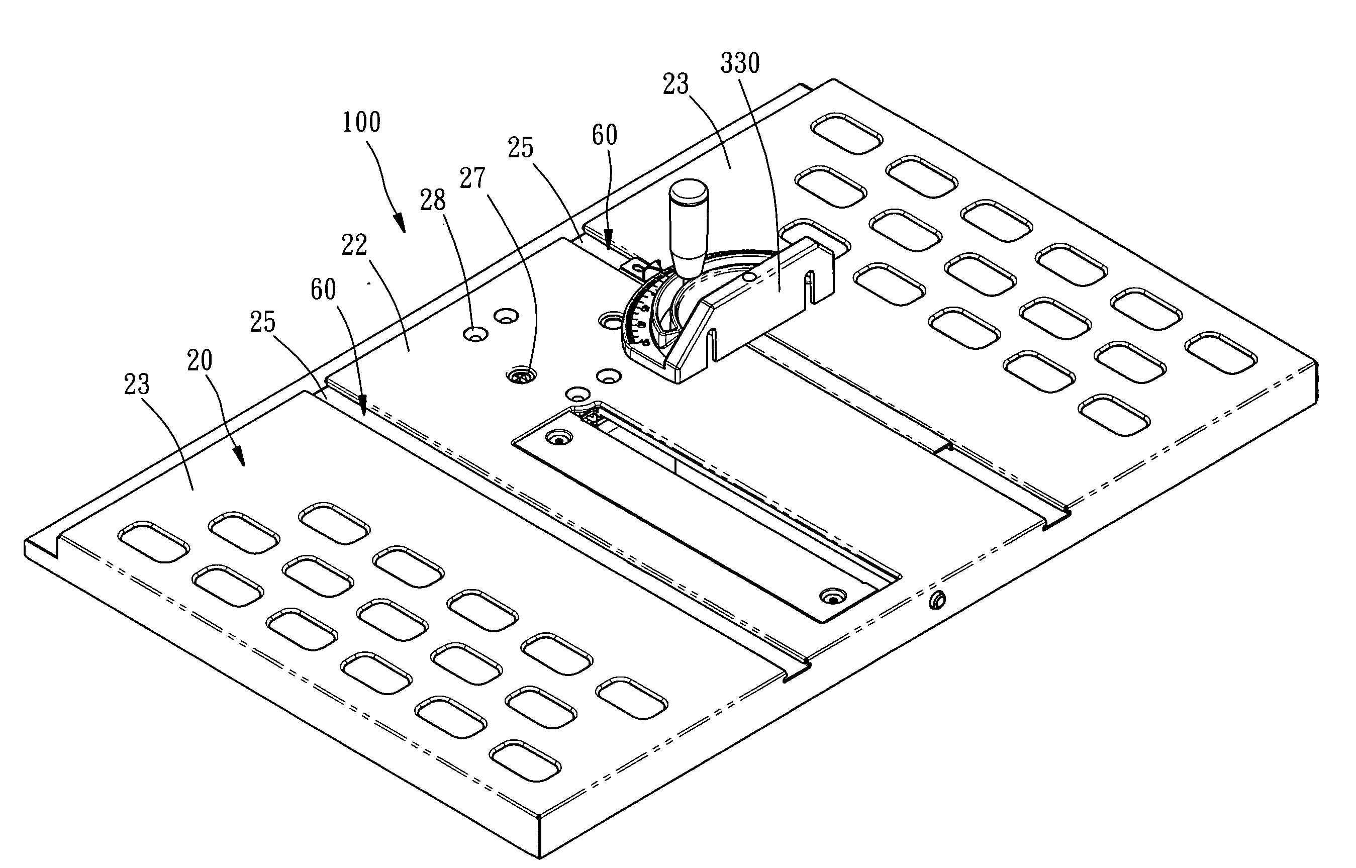
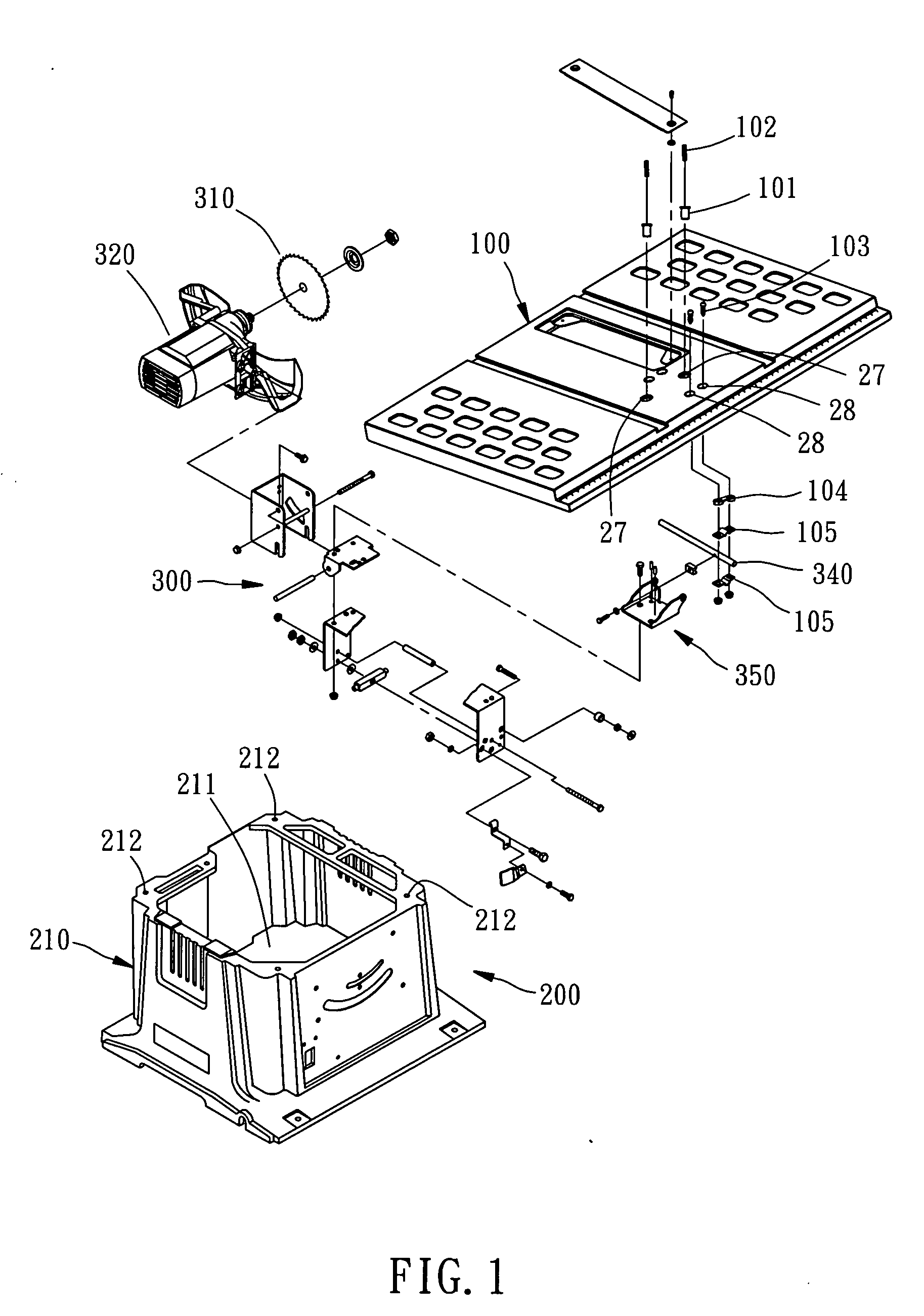
[0018]Referring to FIGS. 1˜6, a worktable 100 in accordance with the preferred embodiment of the present invention is mounted on the top side of a base 210 of a table saw 200. The worktable 100 has its bottom side configured for the mounting of a cutting mechanism 300, which comprises a saw blade 310, a motor 320, a suspension arm 340, and a swinging member 350. The worktable 100 comprises a main worktable plate 20, a reinforcing plate 30, four rib members 40, and two braces 50.

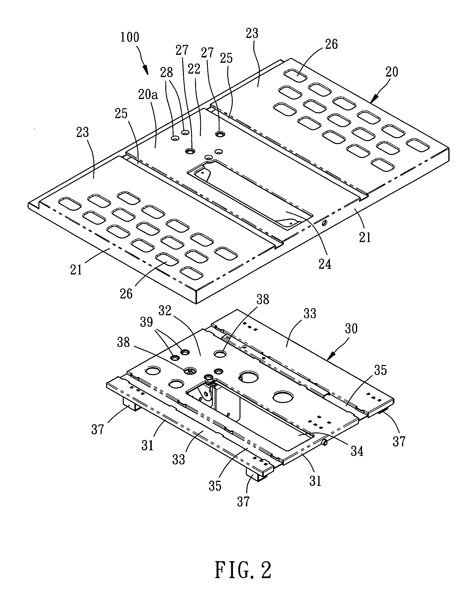
[0019]The main worktable plate 20 is a flat rectangular iron plate worked through stamping and bending processes, having a top surface 20a, a bottom surface 20b, and a downwardly extending peripheral flange 21 at each of the four sides. Further, the main worktable plate 20 is divided into a work region 22 on the middle, and two extension regions 23 at two opposite sides relative to the work region 22. The working region 22 has formed therein a first opening 24, two first punch holes 27, and four first through...


PUM

PropertyMeasurementUnit
sizeaaaaaaaaaa
total weightaaaaaaaaaa
thicknessaaaaaaaaaa

Abstract

A worktable used in a table saw is disclosed to include a main worktable plate made of iron and having a first opening, and a relatively smaller reinforcing plate made of iron and bonded to the bottom side of the main worktable plate to hold the cutting mechanism of the table saw at the bottom side and having a second opening in vertical alignment with the first opening for the passing of the saw blade of the cutting mechanism.

Description

BACKGROUND OF THE INVENTION[0001]1. Field of the Invention[0002]The present invention relates to table saws and more specifically to a worktable for table saw.[0003]2. Description of the Related Art[0004]A regular table saw comprises a base, a worktable mounted on the top side of the base, and a cutting mechanism mounted on the bottom side of the worktable. The cutting mechanism comprises a motor, a saw blade and other related members. The worktable is capable of supporting the total weight of the cutting mechanism. Normally, the worktable is made of aluminum, having a certain thickness for protection against deformation.[0005]An aluminum worktable can support the total weight of a cutting mechanism for table saw. However, in order to support the total weight of a cutting mechanism for table saw and to protect against deformation, an aluminum worktable for table saw must be made having a great wall thickness, resulting in a heavy weight of the worktable. Further, increasing the wall...

Claims


Application Information

Patent Timeline
Patent Type & Authority Applications(United States)
IPC IPC(8): B26D1/18
CPCB23D45/068B23D47/025Y10T83/773
Inventor LIU, CHIA-SHENGCHANG, YU-FENG
Owner DURQ MACHINERY
Learn More