Combustion Chamber with Double Convex Surfaces and Double Concave Surfaces

a combustion chamber and concave surface technology, applied in the field of combustion chambers, can solve the problems of increased emissions, unsightly amount of soot expelled with the engine's exhaust, and designs with a better fuel economy, so as to reduce nox and soot emissions and increase fuel economy

Inactive Publication Date: 2010-05-06
INT ENGINE INTPROP CO LLC
View PDF22 Cites 30 Cited by
  • Summary
  • Abstract
  • Description
  • Claims
  • Application Information

AI Technical Summary

Benefits of technology

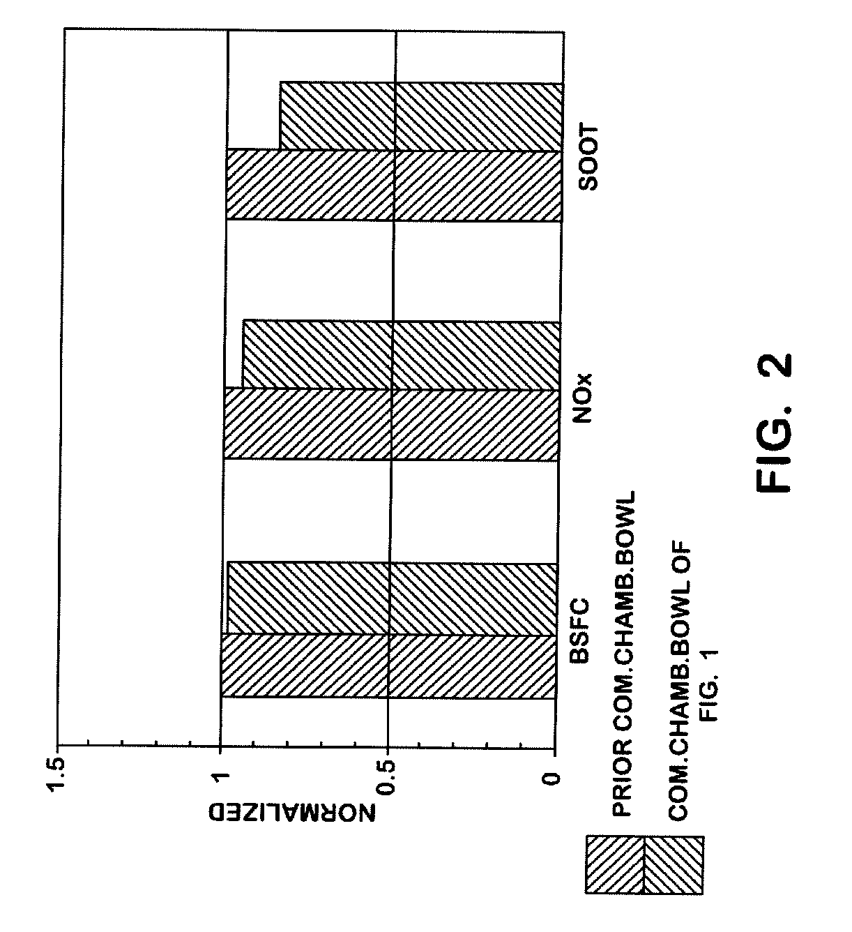
[0007]The present invention provides a piston for a diesel engine wherein the piston includes an improved combustion chamber bowl formed into the piston crown. The present invention provides a diesel engine which operates with reduced NOx and soot emissions, and with an increased fuel economy.

Problems solved by technology

Unfortunately, in the past, engine designs that have reduced emissions have also had worse fuel economy, and designs with a better fuel economy have had increased emissions.
The amount of soot that is expelled with the engine's exhaust is unsightly and generates public pressure to clean up diesel engines.
Further, the amount of soot that is entrained in the engine's lubrication oil can have a deleterious effect on engine reliability.
Soot is very abrasive and can cause high engine wear.
There is additionally a great deal of pressure to reduce the NOx emissions from the engine.
Additionally, doing either of the aforementioned typically reduces engine torque and power outputs.

Method used


Image

  • Combustion Chamber with Double Convex Surfaces and Double Concave Surfaces
  • Combustion Chamber with Double Convex Surfaces and Double Concave Surfaces
  • Combustion Chamber with Double Convex Surfaces and Double Concave Surfaces

Examples


Embodiment Construction

[0016]While this invention is susceptible of embodiment in many different forms, there are shown in the drawings, and will be described herein in detail, specific embodiments thereof with the understanding that the present disclosure is to be considered as an exemplification of the principles of the invention and is not intended to limit the invention to the specific embodiments illustrated.

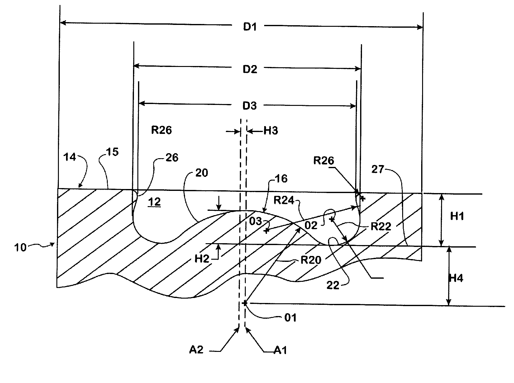
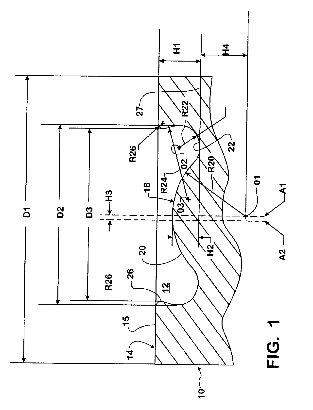
[0017]The piston of the present invention is shown generally at 10 in FIG. 1. A combustion chamber 12 of the present invention is defined in part by a crown 14 having a top surface 15. The crown 14 of the piston 10 defines in part the upper margin of the piston 10.

[0018]It should be noted that the combustion chamber bowl 12 is rotationally symmetrical about a longitudinal axis A1 that is coincident or at an offset with a center axis A2 of the piston 10.

[0019]The various radii (R), diameters (D), and heights (H) that will be described below are clearly indicated in the depiction of FIG. 1.

[0020]Th...


PUM


Abstract

A combustion chamber bowl is defined in a crown of a piston for use in a cylinder of a diesel engine. The combustion chamber bowl includes a center convex spherical portion, first and second annular concave portions and an annular convex portion. The center convex spherical portion is elevated relative to a bottom plane of the combustion chamber bowl and smoothly transitions into the first concave annular portion which transitions smoothly into the second concave annular portion. The second concave annular portion smoothly transitions into the convex annular portion which smoothly transitions into the top surface of the piston crown.

Description

TECHNICAL FIELD OF THE INVENTION [0001]The present invention relates to a combustion chamber for use in a diesel internal combustion engine.BACKGROUND OF THE INVENTION [0002]Many attempts have been made to produce an ideal flow pattern for the charge of air and fuel within the combustion chamber of a diesel internal combustion engine. Considerations that must be taken into effect include, but are not limited to, providing for adequate power generation, minimizing the NOx entrained in the engine exhaust, and minimizing the amount of soot particulate also entrained in the engine exhaust.[0003]It is known that changes in any one of a variety of engine design variables, such as engine compression ratio, combustion chamber shape, fuel injection spray pattern, and other variables can have an affect on both emissions and the fuel economy. Unfortunately, in the past, engine designs that have reduced emissions have also had worse fuel economy, and designs with a better fuel economy have had ...

Claims


Application Information

Patent Timeline
Patent Type & Authority Applications(United States)
IPC IPC(8): F02B23/02
CPCF02B23/0672Y02T10/125Y02T10/12
Inventor LIU, ZHENGBAI
Owner INT ENGINE INTPROP CO LLC
Why Eureka
Try Eureka