System and method for urea decomposition to ammonia in a side stream for selective catalytic reduction

a technology of selective catalytic reduction and side stream, which is applied in the direction of emission prevention, machines/engines, gas turbines, etc., can solve the problems of not meeting the needs of small combustion sources, yamaguchi does not address the time required for complete decomposition and gasification of an aqueous solution of urea, and the emission of nitrogen oxide (“nox”) emissions from small industrial, commercial and electric utility boilers, etc., to achieve the effect of reducing nox emissions

Active Publication Date: 2014-04-10
CECO ENVIRONMENTAL IP INC
View PDF5 Cites 24 Cited by
  • Summary
  • Abstract
  • Description
  • Claims
  • Application Information

AI Technical Summary

Benefits of technology

[0026]In another aspect of the present invention, a method for reducing NOx emissions in the exhaust of a combined cycle gas turbine equipped with a heat recovery boiler and a catalyst effective for NOx reduction is provided, wherein a slip stream of hot flowing exhaust gases is withdrawn from the primary gas flow after the catalyst at a temperature of 500° F. to 900° F. and directed through a fan to a continuous duct into which an aqueous based reagent is injected for decomposition to ammonia gas and the outlet of the continuous duct is connected to an injection grid positioned in the primary exhaust for injection of ammonia gas into the primary exhaust stream at a location upstream of the catalyst.

Problems solved by technology

The reduction of nitrogen oxide (“NOx”) emissions from small industrial, commercial and electric utility boilers, gas turbines, and other lean burn stationary combustion sources continues to be a challenge.
That does not address the needs of small combustion sources where small quantities of ammonia are needed and where smaller decomposition reactors and shorter residence times would be advantageous.
For aqueous based solutions of ammonia, Yamaguchi suggests that 0.5-1.0 seconds are required to vaporize the ammonia solution and Yamaguchi does not address the time required for complete decomposition and gasification of an aqueous solution of urea.
However, the use of steam from a boiler has a penalty associated with removing steam from the heat or power generation process and also with the cost of preparing de-mineralized boiler makeup water to replace the steam used in the vaporization of the aqueous ammonia or its precursor.
Peter-Hoblyn et al. suggest that for SCR, especially at high loads, it is sometimes practical to introduce the aqueous solution of NOx reducing reagent into a slip stream (less than all, e.g., 5-25%) of the exhaust gases to achieve gasification of the reagent prior to mixing with the major or entire portion of exhaust gases.
Peter-Hoblyn et al., however, do not describe how to prevent plugging of the compact pyrolysis chamber with urea decomposition products, especially at higher urea injection rates.
Additionally, it is difficult to see how complete gasification of urea is accomplished in the pyrolysis chamber described by Peter-Hoblyn et al.
Obviously the overall combustor efficiency would be negatively affected if this large quantity of flue gas were bypassed around a heat exchanger.
Lin et al. teach that at high loads with high temperatures the bypass damper can be closed; however, at low loads with low gas temperatures Lin et al. do not describe how this large quantity of bypassed gas would efficiently be brought up to a temperature sufficient for urea gasification.
That can lead to incomplete decomposition of urea and / or to the need for the longer residence times as proposed by Sun et al.
Combustion turbines with the high combustion temperatures and high excess air also produce a significant quantity of nitrogen oxide emissions.
Anderson et al. do not address the fact that many combined cycle turbines have a carbon monoxide catalyst positioned in the high temperature inlet section of the HRSG to oxidize CO in the exhaust to CO2.

Method used


Image

  • System and method for urea decomposition to ammonia in a side stream for selective catalytic reduction
  • System and method for urea decomposition to ammonia in a side stream for selective catalytic reduction
  • System and method for urea decomposition to ammonia in a side stream for selective catalytic reduction

Examples


example

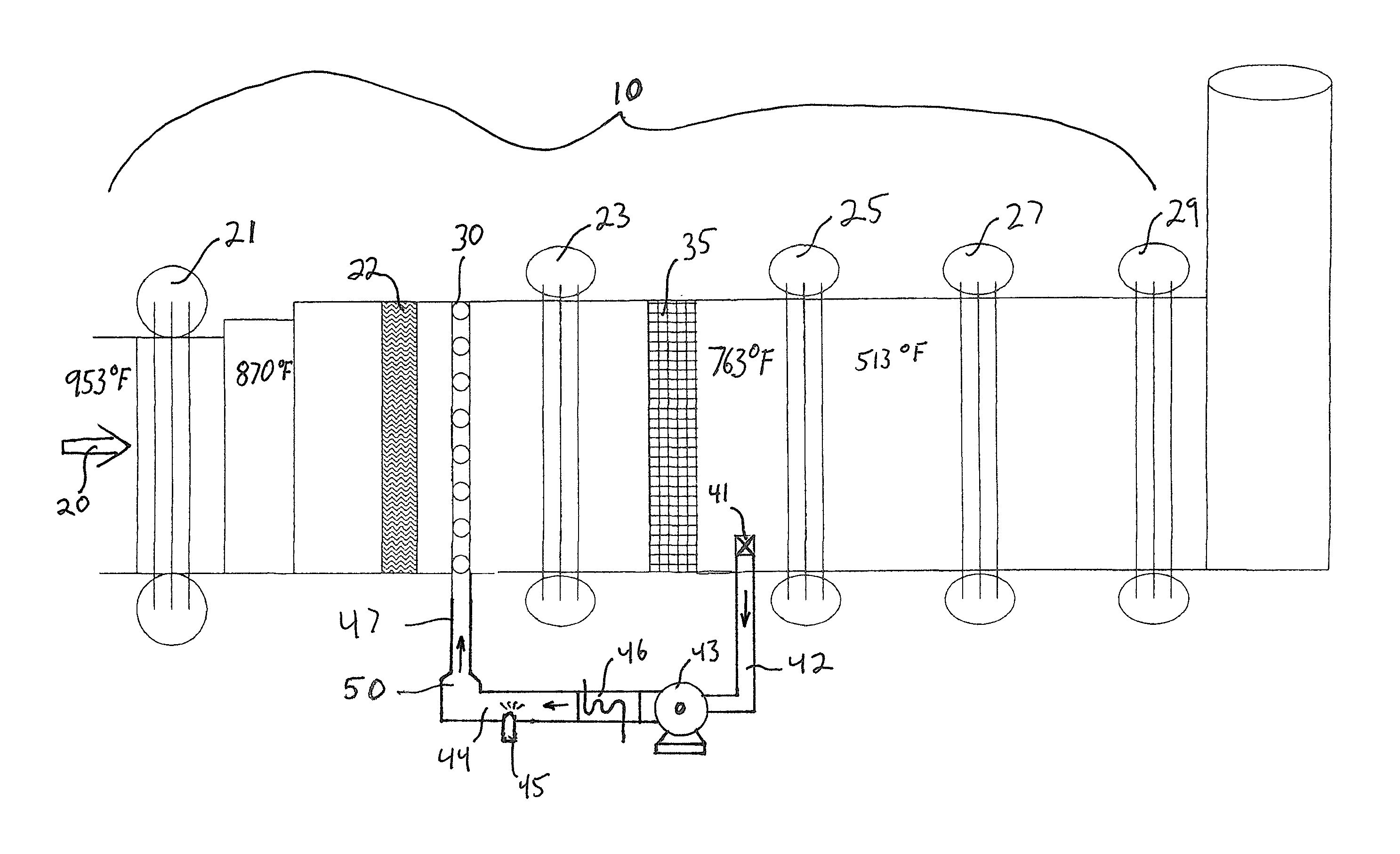
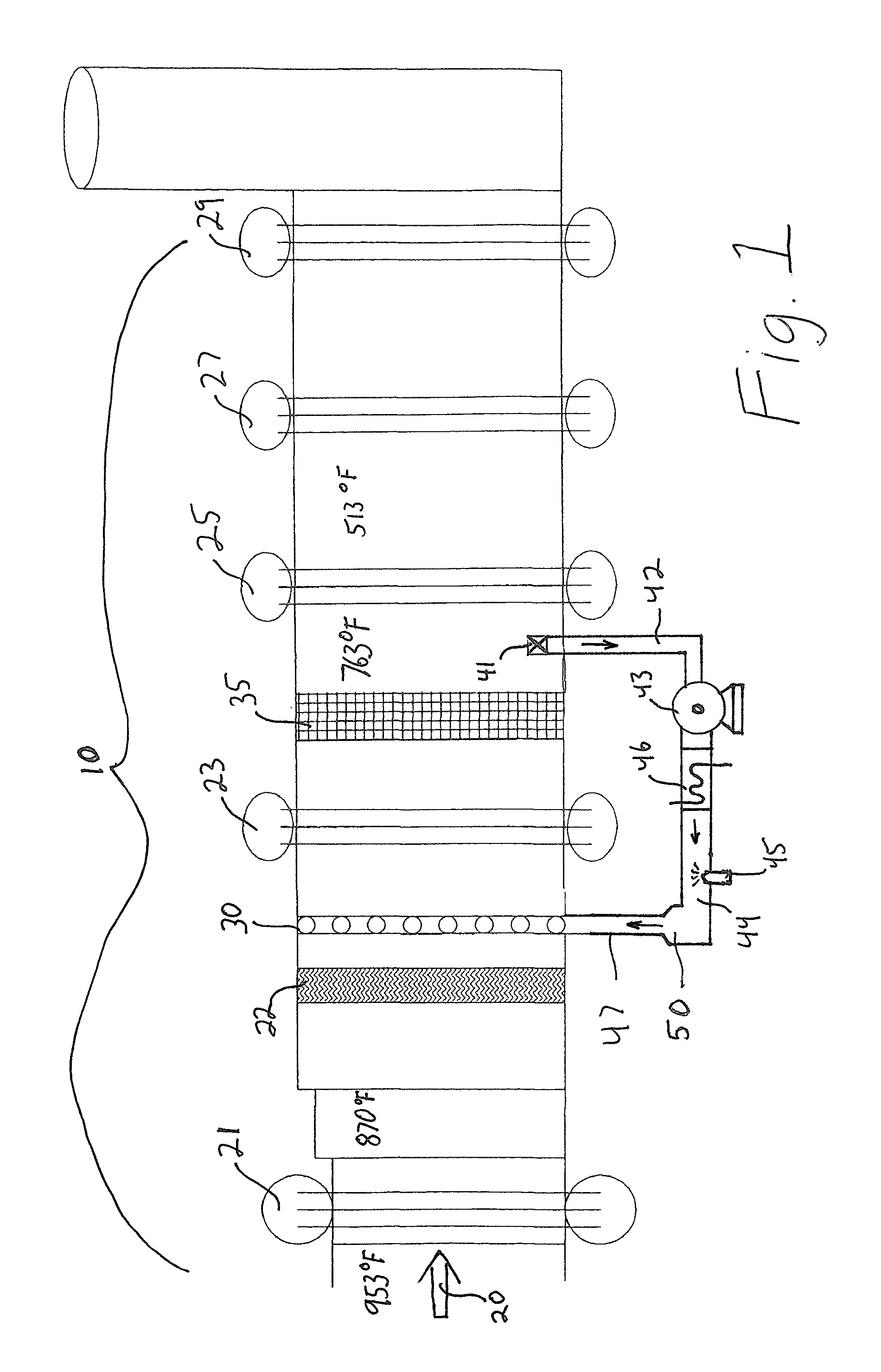
[0034]On a 25 MW gas fired gas turbine the uncontrolled NOx is 42 ppm and control to 2.5 ppm is required. That requires the injection and the decomposition of 7 gallons per hour of 32% urea solution. Hot gases exit the turbine at 953° F. and enter a first high-pressure heat exchanger section (21) of the HRSG. Following the first high pressure heat exchanger section (21) the gases are at a temperature of 870° F. and enter a second heat exchanger section (23). Disposed between the first heat exchanger section (21) and the second heat exchanger section (23) is an ammonia injection grid (AIG) (30) composed of multiple ammonia gas injection pipes with multiple injection orifices on each pipe.

[0035]FIG. 2 presents a typical AIG (30) well know to those skilled in the art. Following the second heat exchanger section (23) the gas temperature is 763° F. In a cavity following the second boiler heat exchanger (23) is disposed an SCR catalyst (35) selected for optimum NOx reduction in a window o...


PUM


Abstract

A method for reducing NOx emissions in the exhaust of a combined cycle gas turbine equipped with a heat recovery boiler and a catalyst effective for NOx reduction, wherein a slip stream of hot flowing exhaust gases is withdrawn from the primary gas flow after the catalyst at a temperature of 500° F. to 900° F. and directed through a fan to a continuous duct into which an aqueous based reagent is injected for decomposition to ammonia gas and the outlet of the continuous duct is connected to an injection grid positioned in the primary exhaust for injection of ammonia gas into the primary exhaust stream at a location upstream of the catalyst.

Description

FIELD OF THE INVENTION[0001]The present invention relates generally to the reduction of nitrogen oxide (NOx) emissions from small industrial, commercial and electric utility boilers and other lean burn stationary combustion sources, especially combined cycle gas turbines with an associated heat recovery boiler. More particularly, the present invention relates to a system and method in which urea is converted to ammonia for use in NOx reduction by selective catalytic reduction (SCR). The present invention is particularly applicable to those combustors know in the art as combined cycle gas turbines with heat recovery boilers.BACKGROUND OF THE INVENTION[0002]The reduction of nitrogen oxide (“NOx”) emissions from small industrial, commercial and electric utility boilers, gas turbines, and other lean burn stationary combustion sources continues to be a challenge. Primary measures, such as low NOx burners, flue gas recirculation, water injection, fuel staging or air staging, need to balan...

Claims


Application Information

Patent Timeline
Patent Type & Authority Applications(United States)
IPC IPC(8): F01N3/08F02C6/18
CPCF02C6/18F01N3/0814F23J15/003F23J15/02F23J2215/10F23J2219/10Y02E20/16
Inventor BRODERICK, JEFFREY MICHAELO'LEARY, KATHRYN V.BRODERICK, R. GIFFORDDALE, JOHN N.VALENTINE, JAMES M.
Owner CECO ENVIRONMENTAL IP INC
Why Eureka
Try Eureka