Exhaust gas cleaning apparatus for lean burn internal combustion engine

a technology of exhaust gas and cleaning apparatus, which is applied in mechanical equipment, machines/engines, electric control, etc., can solve the problems of no fuel being returned, achieve the effect of reducing the nox contained in the exhaust gas in the entire operation region of the engine, reducing the nox reduction performance of the lnt generally, and increasing the temperature of the engin

Active Publication Date: 2008-12-25
DENSO CORP
View PDF6 Cites 23 Cited by
  • Summary
  • Abstract
  • Description
  • Claims
  • Application Information

AI Technical Summary

Benefits of technology

[0023]With the above configuration, it is possible for the exhaust gas cleaning apparatus to reliably reduce the NOx contained in the exhaust gas in the entire operation region of the engine. More specifically, the NOx reduction performance of the LNT generally drops with increase in the temperature of the engine; the temperature of the engine increases both with the rotational speed of the engine and with the load of the engine. When the engine operates in the first operation region, in which both the rotational speed and load of the engine is low, the NOx reduction performance of the LNT is high and it is thus possible to reliably reduce the NOx contained in the exhaust gas only by means of the LNT. On the other hand, when the engine operates in the second operation region, in which either or both of the rotational speed and load of the engine are high, the NOx reduction performance of the LNT drops but the NOx contained in the exhaust gas can be reliably reduced by means of the exhaust gas returning passage.
[0024]The exhaust gas cleaning apparatus further includes detecting means for detecting the deterioration degree of a NOx catalyst of the LNT. As the deterioration degree of the NOx catalyst detected by the detecting means increases, the controller reduces the first operation region of the engine while accordingly expanding the second operation region of the engine.
[0025]With the above configuration, it is possible for the exhaust gas cleaning apparatus to reliably reduce the NOx contained in the exhaust gas regardless of the deterioration degree of the NOx catalyst. More specifically, as the deterioration degree of the NOx catalyst increases, the first operation region of the engine is reduced and the second operation region of the engine is accordingly expanded, so that the exhaust gas cleaning apparatus comes to reduce the NOx depending more on the exhaust gas returning passage and less on the LNT. As a result, the NOx reduction performance of the entire exhaust gas cleaning apparatus can be kept high.

Problems solved by technology

Moreover, since the exhaust gas returning passage is closed when the fuel adding device adds the fuel to the exhaust gas, no fuel is returned to the intake air passage through the exhaust gas returning passage.

Method used


Image

  • Exhaust gas cleaning apparatus for lean burn internal combustion engine
  • Exhaust gas cleaning apparatus for lean burn internal combustion engine
  • Exhaust gas cleaning apparatus for lean burn internal combustion engine

Examples


first embodiment

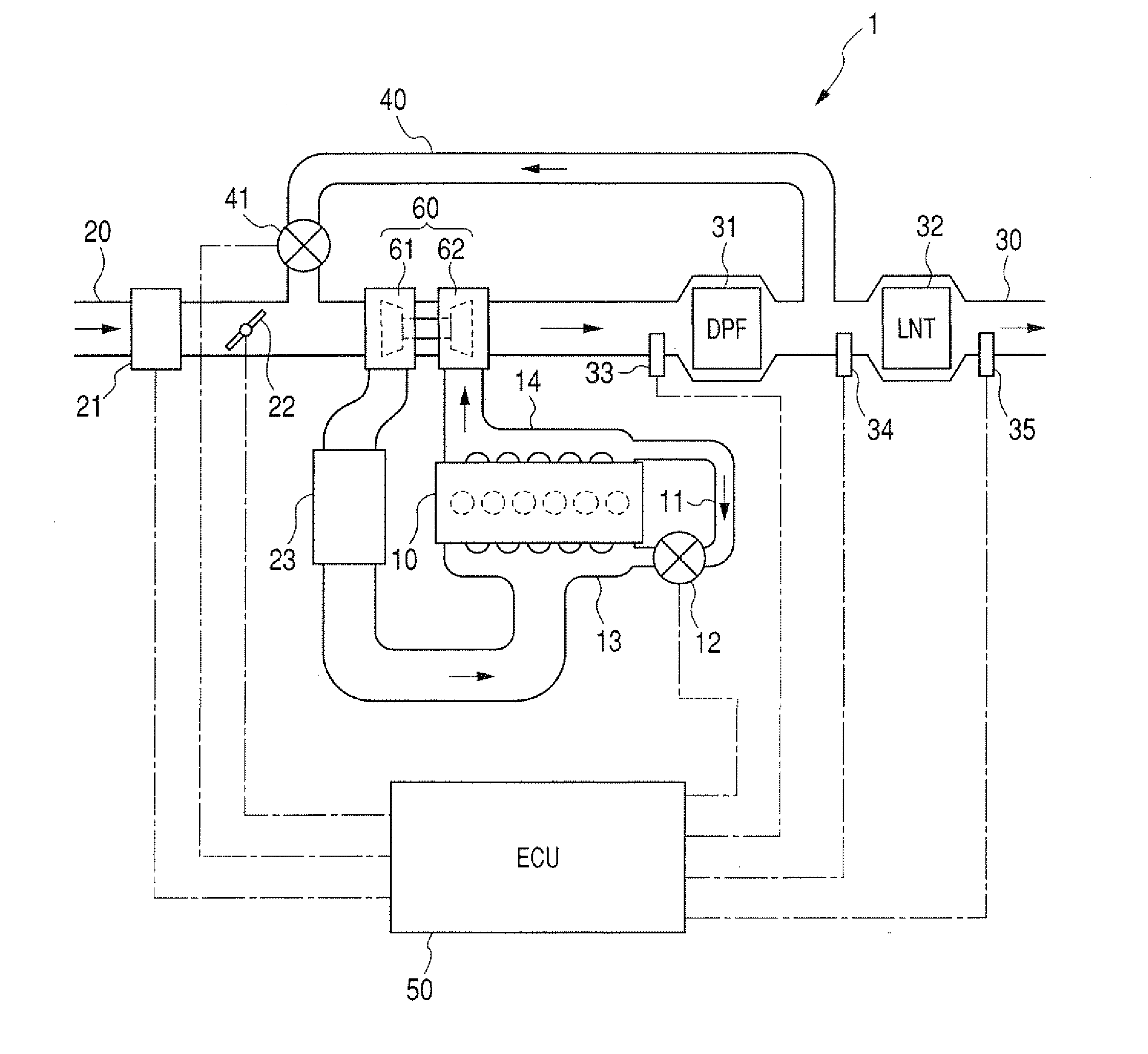
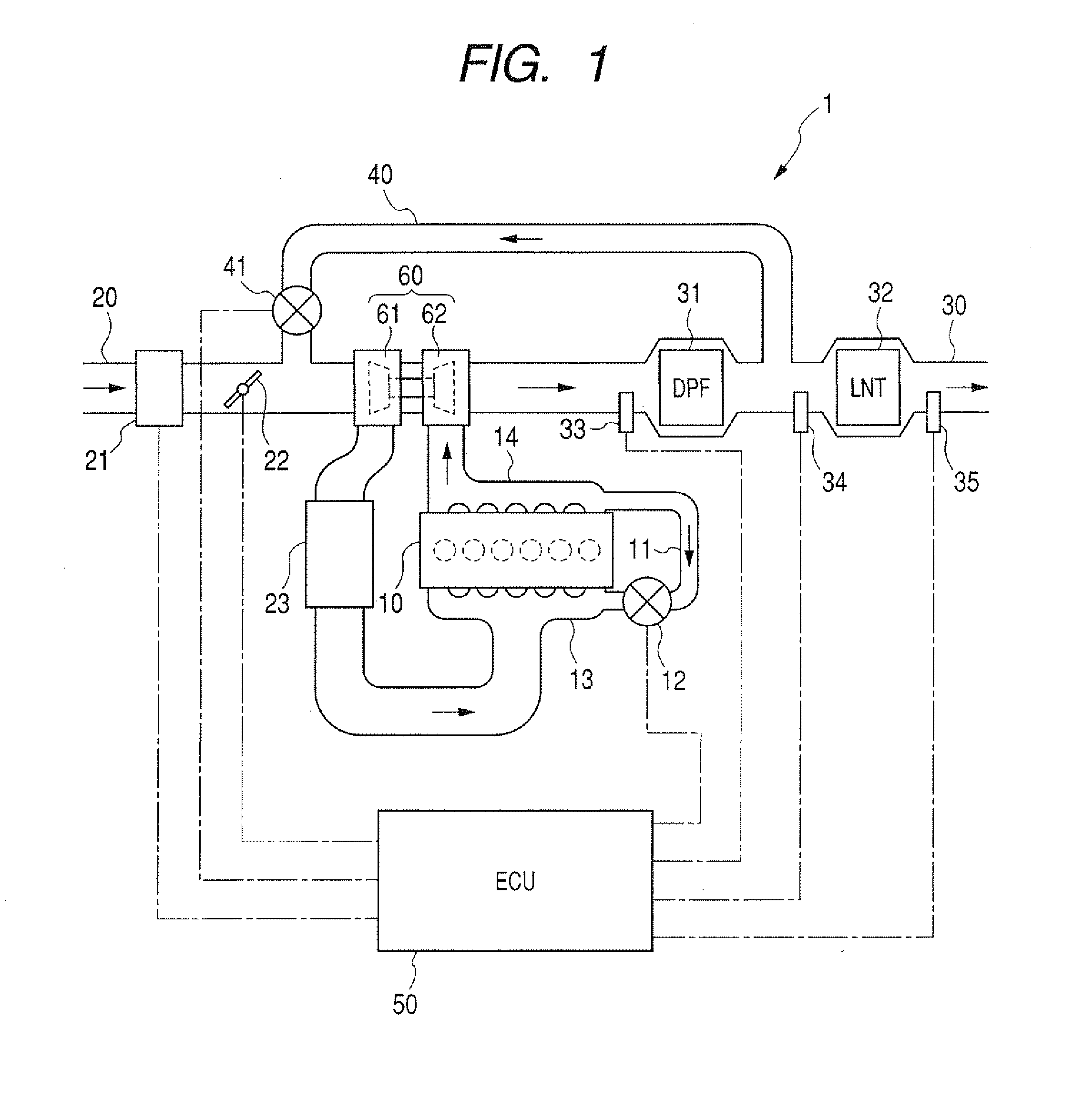
[0047]FIG. 1 shows the overall configuration of an exhaust gas cleaning apparatus 1 according to the first embodiment of the invention.

[0048]The exhaust gas cleaning apparatus 1 is designed to reduce the nitrogen oxides (NOx) contained in the exhaust gas from a diesel engine 10. Around the diesel engine 10, there are also provided an intake pipe 20, an exhaust pipe 30, a low-pressure EGR passage 40, and an Electronic Control Unit (ECU) 50 that controls operations of the diesel engine 10 and the exhaust gas cleaning apparatus 1.

[0049]The diesel engine 10 is supplied with fresh air from an intake manifold 13, and exhausts to an exhaust manifold 14. The fresh air is supplied to the intake manifold 13 from the intake pipe 20, and the exhaust gas from the diesel engine 10 is further discharged from the exhaust manifold 14 to the exhaust pipe 30. The diesel engine 10 is also supplied with fuel by fuel injectors (not shown) which inject the fuel into corresponding cylinders of the diesel e...

second embodiment

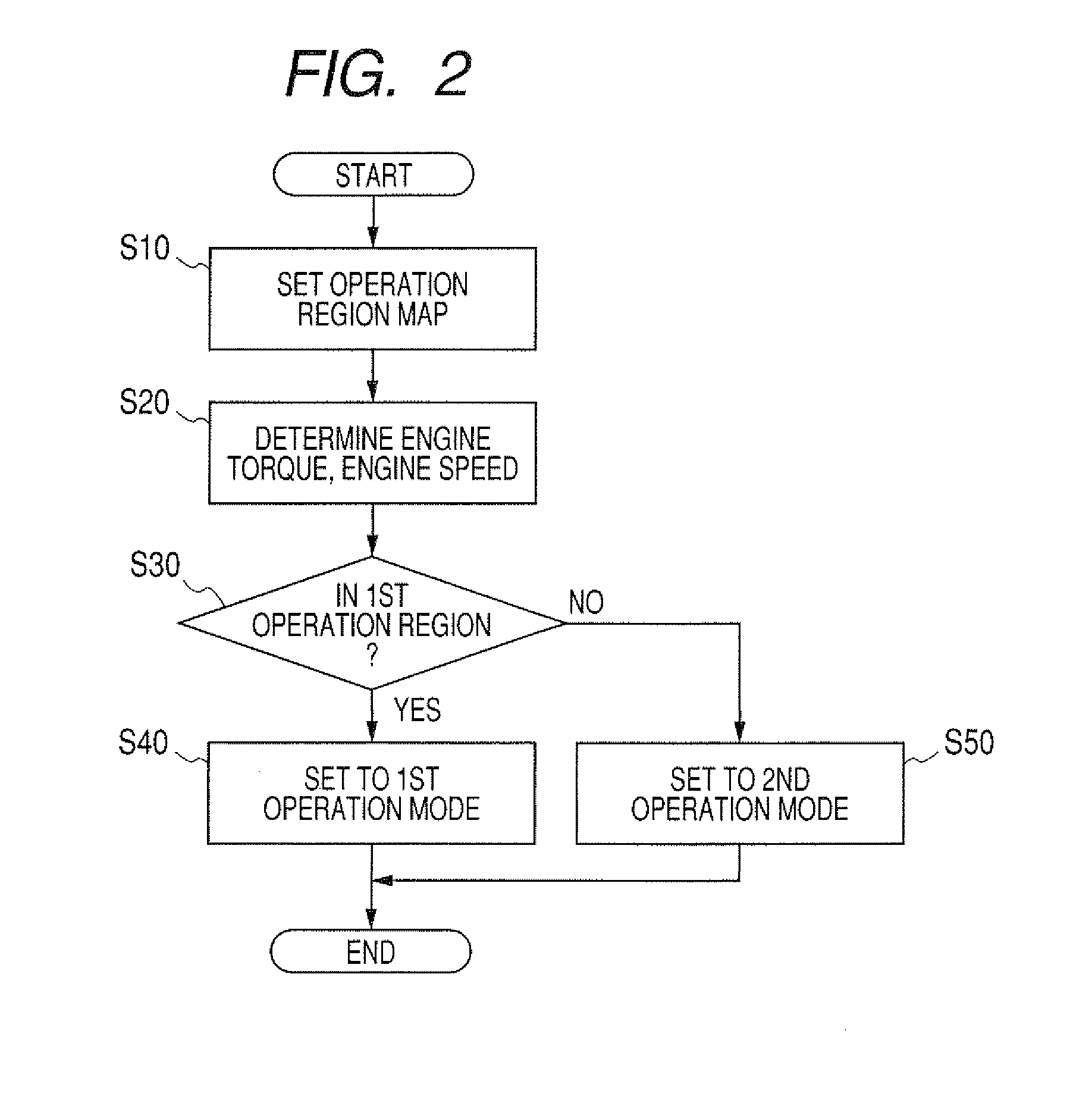
[0080]This embodiment illustrates an operation region map setting process of the ECU 50 which is different from the operation region map setting process according to the first embodiment.

[0081]As described above, in the first embodiment, there is predetermined only the single threshold DD_th by which the entire range of the deterioration degree DD of the NO catalyst is divided into two sub-ranges; the two sub-ranges respectively correspond to the two boundary lines 101 and 102. The ECU 50 selects one of the two boundary lines 101 and 102 according to the sub-range in which the current deterioration degree DD of the NOx catalyst falls.

[0082]In comparison, in the present embodiment, there are predetermined N (N is an integer greater than 1) thresholds by which the entire range of the deterioration degree DD of the NOx catalyst is divided into (N+1) sub-ranges; to each of the (N+1) sub-ranges, there is assigned a boundary line. Accordingly, the number of the boundary lines is (N+1).

[00...


PUM


Abstract

An exhaust gas cleaning apparatus includes a LNT, a fuel adding device, an exhaust gas returning passage, and a controller. The LNT is provided in an exhaust gas passage of an engine. The fuel adding device is located upstream of the LNT to add fuel to exhaust gas flowing through the exhaust pipe. The exhaust gas returning passage branches off from the exhaust gas passage at a position downstream of the fuel adding device. The controller controls the apparatus to selectively operate in one of first and second modes according to the operating condition of the engine. In the first mode, the fuel adding device adds the fuel to the exhaust gas with the exhaust gas returning passage closed; in the second mode, the exhaust gas is partially returned to an intake air passage through the exhaust gas returning passage without the fuel being added by the fuel adding device.

Description

CROSS-REFERENCE TO RELATED APPLICATION[0001]This application is based on and claims priority from Japanese Patent Application No. 2007-162197, filed on Jun. 20, 2007, the content of which is hereby incorporated by reference in its entirety into this application.BACKGROUND OF THE INVENTION[0002]1 Technical Field of the Invention[0003]The present invention relates to an exhaust gas cleaning apparatus for cleaning the exhaust gas from a lean burn internal combustion engine.[0004]2 Description of the Related Art[0005]In a lean burn internal combustion engine, such as a diesel engine or a lean burn gasoline engine, combustion is made at an air / fuel ratio higher than the stoichiometric air / fuel ratio. Due to the excessive air in the air / fuel mixture, it is ineffective to reduce the nitrogen oxides (NOx) contained in the exhaust gas by means of a three-way catalyst. Accordingly, a Lean NOx Trap (LNT) is used instead to reduce the NOx contained in exhaust gas. The LNT is configured to absor...

Claims


Application Information

Patent Timeline
Patent Type & Authority Applications(United States)
IPC IPC(8): F01N3/00
CPCF01N3/021F01N3/0814F01N9/00F02B3/06F02B29/0406F02B37/00F02D41/005F02D41/0235F02D41/027F02M25/0707F02M25/0709F02M25/0718Y02T10/47F02M26/05F02M26/06F02M26/15Y02T10/40
Inventor YOKOYAMA, MASAKUNIKAWAMURA, JUN
Owner DENSO CORP
Why Eureka
Try Eureka