Exhaust Gas Management System

Inactive Publication Date: 2020-10-15
BORGWARNER EMISSIONS SYST SPAIN S L U
View PDF0 Cites 0 Cited by
  • Summary
  • Abstract
  • Description
  • Claims
  • Application Information

AI Technical Summary

Benefits of technology

[0004]In particular, one of said heat exchangers allows the cooling of the exhaust gas and the subsequent recirculation thereof to the intake manifold of the engine. Said heat exchanger, or EGR (Exhaust Gas Recirculation) exchanger, is located close to the naturally aspirated engine, with a recirculation valve, or EGR valve, being placed between said EGR exchanger and the intake manifold of the naturally aspirated engine.
[0005]The close positioning of the EGR exchanger to the intake manifold of the engine is due to the fact that introducing gas back into the intake manifold requires overpressure in the recirculated gas so that it can overcome the press

Problems solved by technology

In this case, the heat exchanger works as a heat recovery unit and must cause the lowest pressure drop so as not to increase exhaust pressure, which would reduce engine performance.
There is an interest in the heat recovery unit being located downstream of the exhaust line because space is very limited in the engine compartment.
However, given that the behavior of an inter

Method used


Image

  • Exhaust Gas Management System
  • Exhaust Gas Management System
  • Exhaust Gas Management System

Examples


first embodiment

of the Invention

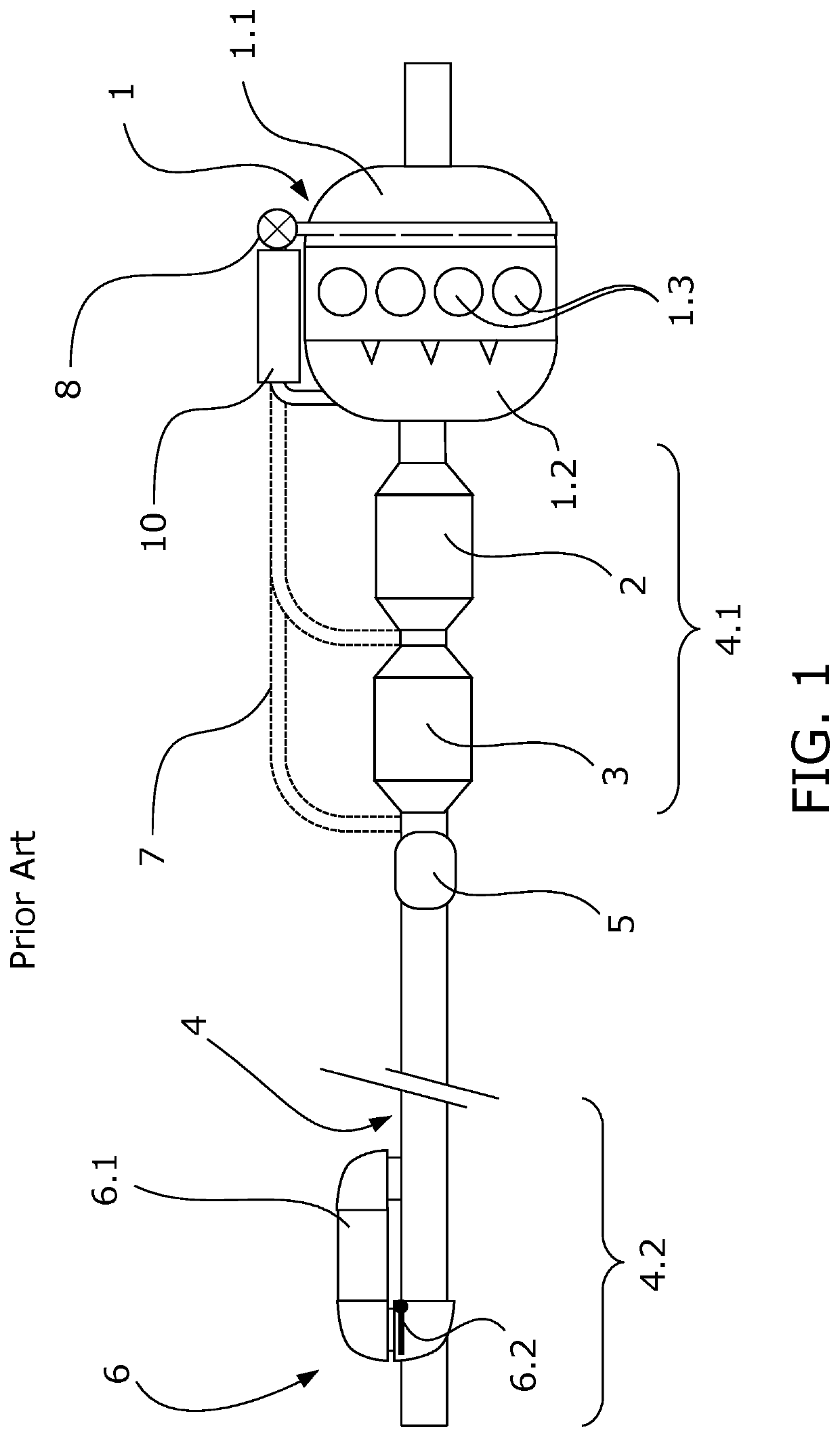
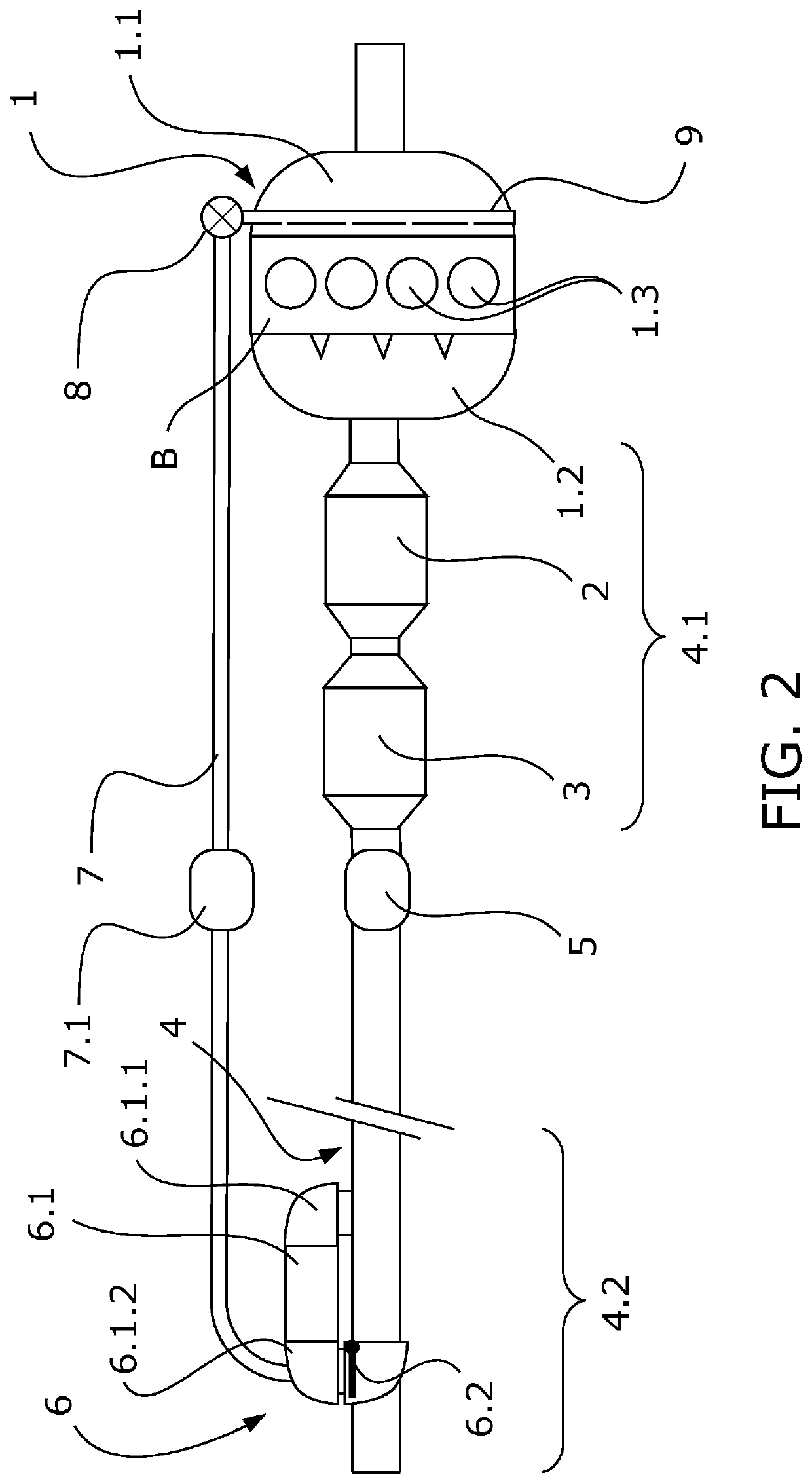
[0072]FIG. 2 shows a first embodiment of the invention in which the specific heat exchanger (10) for EGR gas which was located right at the inlet of the intake manifold (1.1) is dispensed with and the exchanger of the recovery module (6) is established as a heat exchanger both for recovering heat and for cooling recirculated EGR gas. The rest of the elements in common with FIG. 1 are considered to have been described when the system according to the state of the art was described.

[0073]For this purpose, the outlet of the exchanger is established in the second port (6.1.2) and is communicated with the valve (8) for regulating the recirculated gas flow by means of a recirculation duct (7).

[0074]Although this heat recovery module (6) is located adjacent to the second end (4.2) of the exhaust duct (4) with a pressure close to atmospheric pressure, it has surprisingly been verified that in naturally aspirated gasoline engines, when the valve (8) for regulating the recircu...

second embodiment

of the Invention

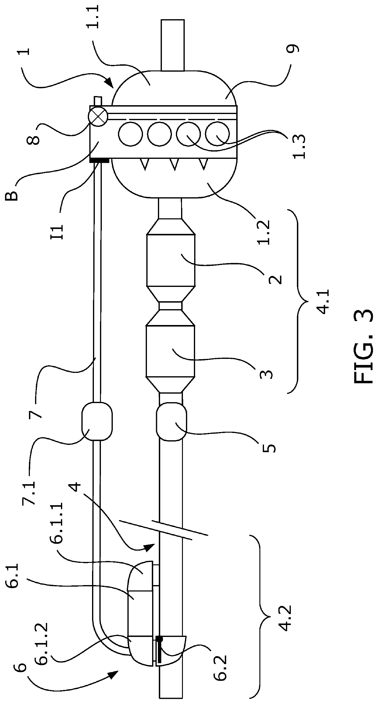
[0087]FIG. 3 schematically shows a second embodiment in which most the elements have already been described in the first embodiment, whereby only those different elements with respect to the first embodiment will be described below.

[0088]In this embodiment, the valve (8) for regulating the recirculated gas flow or EGR gas has been installed integrated in the engine block (B) such that the manufacture of certain parts is avoided given that some surfaces of the valve (8) are formed by said engine block (B), and most importantly the valve (8) is located even closer to the combustion chambers (1.3), drastically reducing response inertia when recirculated gas is to be fed to the intake of the internal combustion engine (1).

[0089]Said FIG. 3 also shows a first attachment interface (I1) which allows the attachment between the recirculation duct (7) and the engine block (B) such that the recirculation duct (7) and the valve (8) for regulating the recirculated gas flow which ...

third embodiment

of the Invention

[0092]FIG. 5 schematically shows a third embodiment of the invention in which the bypass valve (6.2) is located upstream the heat recovery module (6) following the direction of flow of the exhaust gas along the exhaust duct (4), that is, on the side where the first port (6.1.1) is located. Additionally, the end of the heat exchanger (6.1) connected to the recirculation duct (7) is now upstream of the module (6). The connection is established in the first port (6.1.1).

[0093]In FIG. 5, the bypass valve (6.2) is depicted in the second position, which establishes the passage of the gas through the exhaust duct (4) where the hot gas circulating through the exhaust duct (4) continues until the second end (4.2) of the exhaust duct (4) with free access to the atmosphere. In this position of the flap of the bypass valve (6.2), there is no heat recovery save a small unwanted recovery value through the access of the hot gas into the tube bundle of the heat exchanger. Neverthele...


PUM


Abstract

The present invention relates to an exhaust gas management system which allows cooled exhaust gas recirculation as well as heat recovery through a single integrated module, located downstream of the exhaust line. Additionally, the present invention relates to a propulsion system wherein the cooled exhaust gas is recirculated to the intake manifold of an internal combustion engine.

Description

OBJECT OF THE INVENTION[0001]The present invention relates to an exhaust gas management system which allows cooled exhaust gas recirculation as well as heat recovery through a single integrated module, located downstream of the exhaust line.[0002]Additionally, the present invention relates to a propulsion system wherein the cooled exhaust gas is recirculated to the intake manifold of an internal combustion engine.BACKGROUND OF THE INVENTION[0003]Naturally aspirated propulsion systems by means of an internal combustion engine which comprise the functions of cooled exhaust gas recirculation as well as heat recovery are known today. This is achieved for example by means of corresponding heat exchangers for each of these functions.[0004]In particular, one of said heat exchangers allows the cooling of the exhaust gas and the subsequent recirculation thereof to the intake manifold of the engine. Said heat exchanger, or EGR (Exhaust Gas Recirculation) exchanger, is located close to the nat...

Claims


Application Information

Patent Timeline
IPC IPC(8): F02M26/21F01N13/10F02M35/10F02M26/22
CPCF01N13/10F02M26/21F02M26/22F02M35/10222F01N3/043F01N5/02F01N13/08F02M26/14F02M26/25F02M26/28F02G5/02F02M26/12F02M26/15F02M26/71Y02T10/12
Inventor GONZÁLEZ TABARÉS, IAGOPÉREZ MAURICIO, XURXOHERMIDA DOMÍNGUEZ, XOAN XOSÉ
Owner BORGWARNER EMISSIONS SYST SPAIN S L U
Why Eureka
Try Eureka