Fuel supply device for internal combustion engine

a fuel supply device and internal combustion engine technology, applied in the direction of machines/engines, output power, electric control, etc., can solve the problem that the formation of deposits around the nozzle cannot be suppressed, and achieve the effect of reducing temperature, reducing feed pressure, and reducing the temperature of the injector

Inactive Publication Date: 2013-07-11
TOYOTA JIDOSHA KK
View PDF13 Cites 2 Cited by
  • Summary
  • Abstract
  • Description
  • Claims
  • Application Information

AI Technical Summary

Benefits of technology

[0010]According to one aspect of the present invention, when the valve overlap between an intake valve and an exhaust valve of an internal combustion engine becomes larger than a determination value, a temperature reduction control for reducing temperature of an injector is performed as a control in supplying fuel adjusted to a feed pressure to the injector for injecting fuel into an intake port. When the valve overlap between the intake valve and the exhaust valve becomes equal to or larger than the determination value, the amount of exhaust gas flowing back from a combustion chamber to the intake port increases and the temperature of the intake port and that of the injector tend to increase due to heat of the exhaust gas. Since the vicinity of a nozzle of the injector is exposed to heat from the intake port when the temperature of the intake port increases, the vicinity of the nozzle of the injector is placed in a high-temperature environment. Further, the vicinity of the nozzle of the injector is placed in a high-temperature environment also when the temperature of the injector increases and heat of the injector itself is transferred to the vicinity of the nozzle. If the temperature of the injector is reduced by performing the above temperature reduction control under these conditions, the vicinity of the nozzle is less likely to be placed under a high-temperature condition by in accordance with the reduction in heat transfer from the injector itself to the vicinity of the nozzle. Therefore, the formation of deposit around the nozzle is suppressed.
[0011]According to one aspect of the present invention, a temperature reduction control for reducing temperature of an injector is performed as a control in supplying fuel adjusted to a feed pressure to the injector for injecting fuel into an intake port prior to initiation of a stopping process of an internal combustion engine. Immediately after the stopping process of the internal combustion engine is completed, the engine temperature further increases since the cooling function by cooling water of the engine does not work with a high engine temperature maintained. At this time, heat of the internal combustion engine itself is transferred to the intake port and the injector, whereby the temperature of the intake port and that of the injector tend to increase. Since the vicinity of a nozzle of the injector is exposed to heat from the intake port when the temperature of the intake port increases, the vicinity of the nozzle of the injector is placed in a high-temperature environment. Further, the vicinity of the nozzle of the injector is placed in a high-temperature environment also when the temperature of the injector increases and heat of the injector itself is transferred to the vicinity of the nozzle. However, the temperature of the injector is reduced through the execution of the above temperature reduction control before the stopping operation of the internal combustion engine, which is a cause of these circumstances, is initiated. If the temperature of the injector is reduced in this way, heat of the injector itself is less likely to be transferred to the vicinity of the nozzle and the vicinity of the nozzle is less likely to be placed under a high-temperature condition by that much when the engine temperature increases immediately after the stopping operation of the internal combustion engine is completed. As a result, the formation of deposit around the nozzle of the injector immediately after the stopping operation of the internal combustion engine is completed is suppressed.
[0012]In the above temperature reduction control, specifically, the feed pressure may be reduced in supplying the fuel adjusted to the feed pressure to the injector or to increase a fuel injection time of the injector.
[0013]In the case of reducing the feed pressure as described above, the particle size of atomized fuel injected from the nozzle of the injector increases due to reduction of the feed pressure, wherefore particles of the atomized fuel are more likely to reach the intake port. When the particles of the atomized fuel reach the intake port and are vaporized there, heat from the intake port is absorbed through latent heat of vaporization of the fuel, whereby the temperature of the intake port is effectively reduced. As a result, heat of the intake port is less likely to be transferred to the injector, and the temperature of the injector is reduced, accordingly.
[0014]Further, in the case of increasing the fuel injection period as described above, the fuel passes through the injector over a longer period in injecting the fuel from the injector and the injector is effectively cooled by that fuel. The temperature of the injector is reduced through such cooling of the injector by the fuel.
[0015]An execution condition of the above temperature reduction control is preferably that at least one of parameters including a cooling water temperature, a rotation speed and a load of the internal combustion engine becomes equal to or higher than a determination value set for each of the parameters. When the parameters such as the cooling water temperature, the rotation speed and the load of the internal combustion engine are high values, the temperature of the injector tends to increase. Thus, by performing the temperature reduction control when the above execution condition is met, the temperature of the injector can be reduced in a situation where the temperature of the injector tends to increase.

Problems solved by technology

However, even if the fuel is injected from the injector with the feed pressure increased as described above, the vicinity of the nozzle of the injector is inevitably placed in a high-temperature environment, wherefore the formation of deposit around the nozzle cannot be suppressed.

Method used


Image

  • Fuel supply device for internal combustion engine
  • Fuel supply device for internal combustion engine
  • Fuel supply device for internal combustion engine

Examples


Embodiment Construction

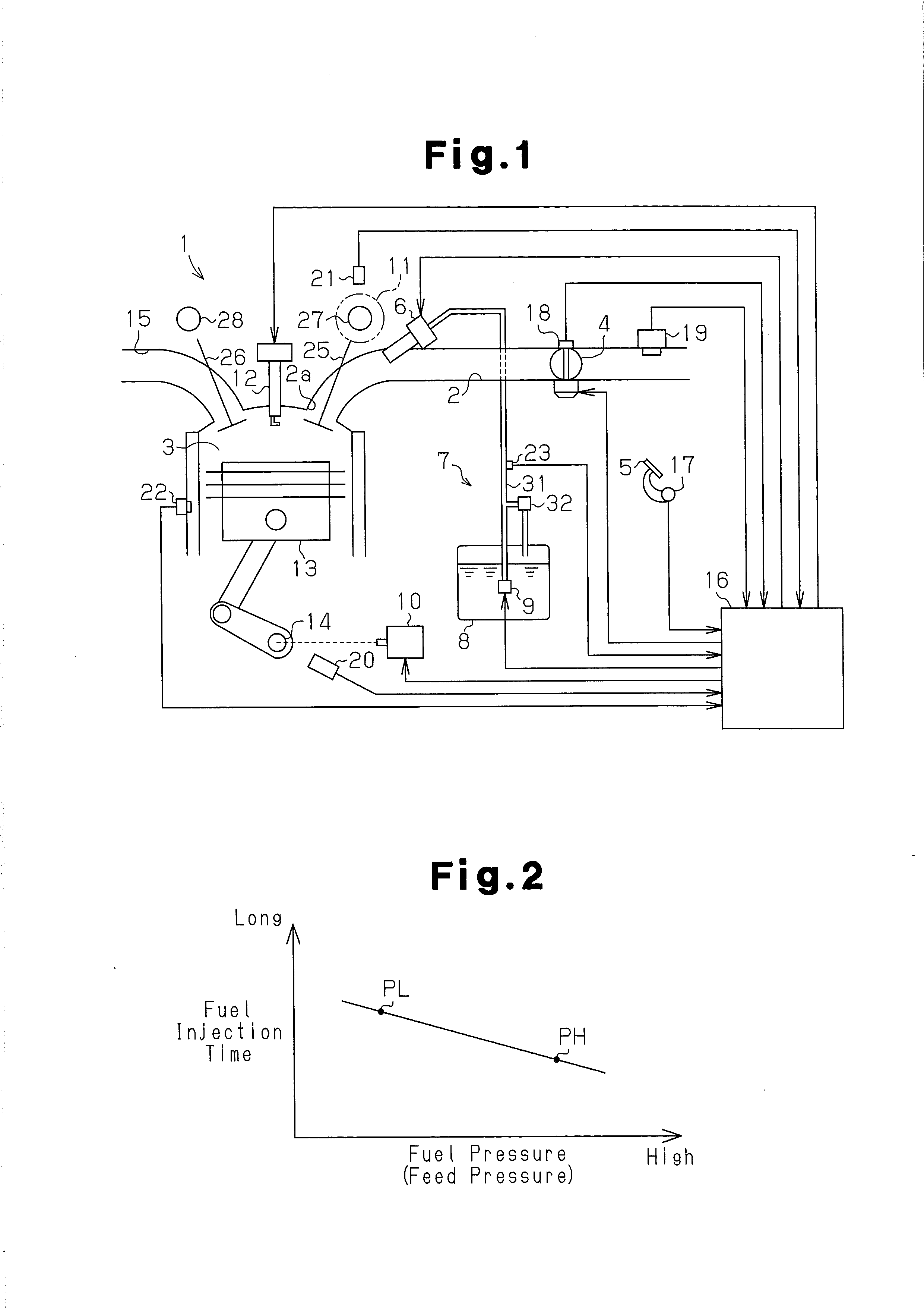
[0027]Hereinafter, a fuel supply device of an automotive engine according to one embodiment of the present invention will be described with reference to FIGS. 1 to 11.

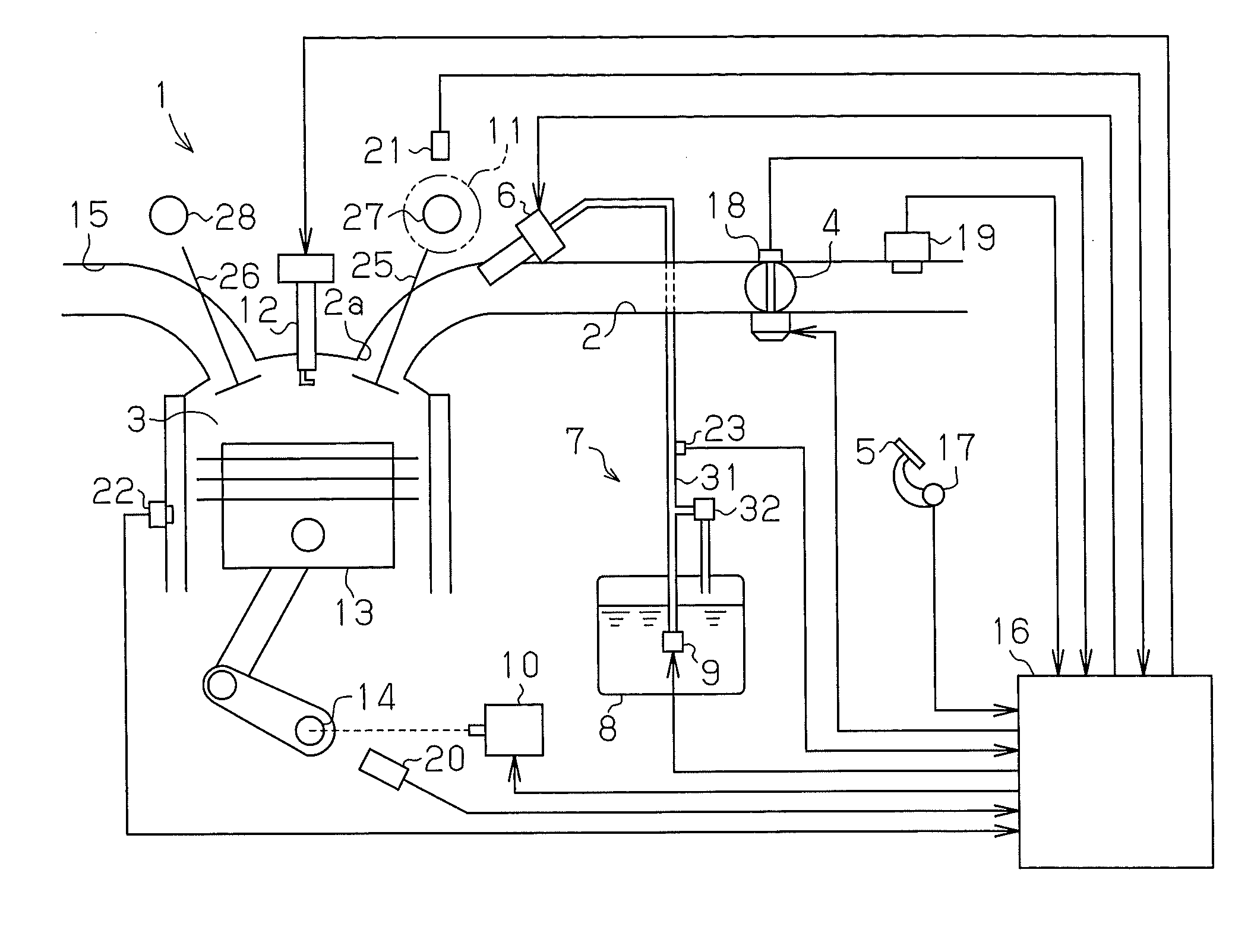
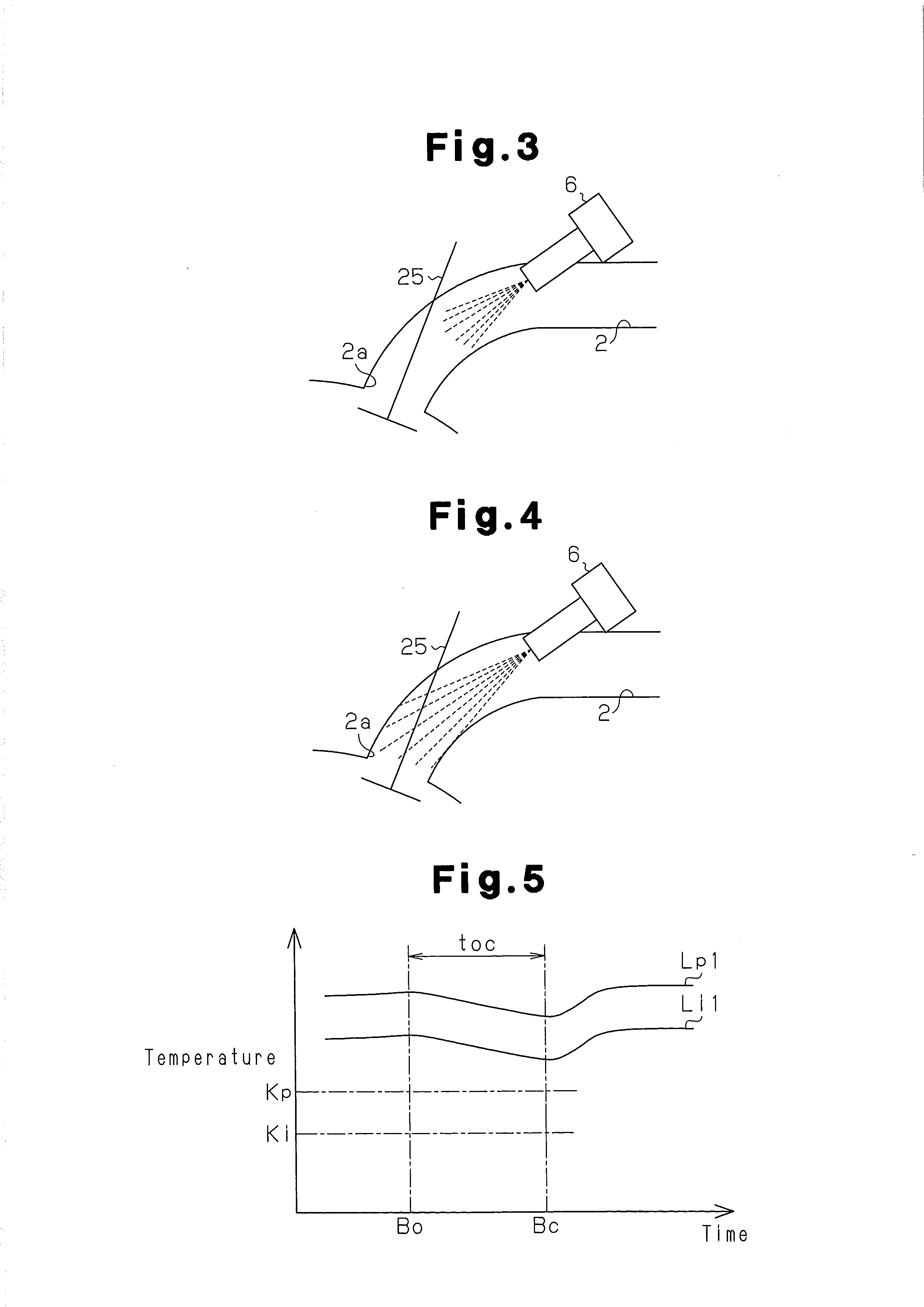
[0028]A throttle valve 4, which is opened and closed to adjust the amount of air taken into a combustion chamber 3 (intake air amount), is provided in an intake passage 2 of an engine 1 shown in FIG. 1. The opening degree of this throttle valve 4 (throttle opening degree) is adjusted according to the depression amount (accelerator operation amount) of an accelerator pedal 5 depressed by the driver of an automobile. Further, the engine 1 includes an injector 6 for injecting fuel toward an intake port 2a of the combustion chamber 3 from the intake passage 2 and a fuel supply device 7 for supplying the fuel adjusted to a feed pressure to that injector 6.

[0029]The fuel supply device 7 includes a feed pump 9 for drawing fuel stored in the fuel tank 8, a fuel pipe 31 for feeding the fuel drawn by the feed pump 9 to the injec...


PUM


Abstract

A temperature reduction control for reducing the temperature of an injector is performed through first to third fuel supply control routines executed by an electronic control device. When the temperature of the injector is reduced by the execution of the temperature reduction control, heat transfer to the vicinity of the nozzle of the injector is reduced. Since the vicinity of the nozzle of the injector is less likely to be placed in a high-temperature environment by in accordance with reduction in heat transfer to the vicinity of the nozzle of the injector, the formation of deposit around the nozzle of the injector is suppressed.

Description

[0001]This is a 371 national phase application of PCT / JP2011 / 059679 filed 20 Apr. 2011, the contents of which are incorporated herein by reference.FIELD OF THE INVENTION[0002]The present invention relates to a fuel supply device for an internal combustion engine.BACKGROUND OF THE INVENTION[0003]An internal combustion engine mounted in a vehicle such as an automobile includes an injector for injecting fuel into an intake port and a fuel supply device for supplying fuel adjusted to a feed pressure to the injector.[0004]In the above injector, fuel and exhaust gas flowing back from a combustion chamber to the intake port adheres around the nozzle of the injector. If the vicinity of the nozzle to which the fuel and the exhaust gas adhere is placed in a high-temperature environment, deposit is formed, for example, by the burning of fuel and exhaust gas adhering around the nozzle. If the deposit is formed around the nozzle of the injector, the opening area of the nozzle may be made smaller...

Claims


Application Information

Patent Timeline
Patent Type & Authority Applications(United States)
IPC IPC(8): F02M69/04
CPCF02M69/044F02D13/0238F02D13/0261Y02T10/18F02D41/042F02D41/065F02D2041/224F02M69/04Y02T10/12
Inventor NISHIMURA, TAICHIKANEKO, RIHITO
Owner TOYOTA JIDOSHA KK
Why Eureka
Try Eureka