Exhaust gas purifier for use in internal combustion engine

a technology for exhaust gas purifiers and internal combustion engines, which is applied in the direction of machines/engines, electrical control, separation processes, etc., can solve the problems of reducing the amount of reducers (residual co, hc, etc.) which have not been able to adequately purify nox in the exhaus

Inactive Publication Date: 2004-04-13
MITSUBISHI MOTORS CORP
View PDF42 Cites 24 Cited by
  • Summary
  • Abstract
  • Description
  • Claims
  • Application Information

AI Technical Summary

Benefits of technology

According to an exhaust purifier of the present invention for use in an internal combustion engine, when the exhaust air-fuel ratio of the engine is switched from a lean air-fuel ratio to a stoichiometric air-fuel ratio or a rich air-fuel ratio, reducer-supplying means supplies a reducer for reducing NOx released from an NOx catalyst device to reduce NOx released from the catalyst device without impairing exhaust gas characteristics.
Since NOx released from the NOx catalyst device is reduced by means of the supplied reducer, NOx is not released into the atmosphere, thereby suppressing impairment in THE exhaust gas performance.
Thus, NOx released from the catalyst device can be reliably reduced without need of a complicated device.
According to the exhaust purifier of the present invention for use in an internal combustion engine, when NOx-releasing means is operated to create a low-oxygen-concentration exhaust atmosphere in order to release NOx from a NOx catalyst, the reducer-supplying means additionally supplies a reducer for reducing NOx released into an exhaust path, at a predetermined timing during operation of the NOx-releasing means, thereby reducing NOx released from the NOx catalyst without impairment of the exhaust gas characteristics.
Since NOx released from the catalyst device is reduced by means of the supplied reducer, NOx is not released into the atmosphere, thereby suppressing impairment in the exhaust gas performance.
The NOx-releasing means has a regenerative function for establishing a rich air-fuel ratio in the exhaust gas for a first predetermined period of time and subsequently establishing a near stoichiometric air-fuel ratio for a second predetermined period of time when NOx occluded on the NOx catalyst is to be released. The reducer-supplying means operates when the NOx-releasing means causes switching of an air-fuel ratio in the exhaust gas to a rich air-fuel ratio. The exhaust purifier includes deterioration-detecting means for detecting the degree of deterioration of the NOx catalyst, and correction means for making correction to prolong the second predetermined period of time associated with the regenerative function of the NOx-releasing means or to shorten the operating period of time of the reducer-supplying means as the degree of deterioration of the NOx catalyst detected by the deterioration-detecting means increases.

Problems solved by technology

The lean-burn engine has a problem in that a conventional three-way catalytic converter cannot sufficiently purify NOx in an exhaust gas during a lean combustion due to its purification characteristics.
However, the technique disclosed in the above publication encounters a difficulty in establishing coincidence between a ratio at which NOx is reduced and that at which NOx is released.
However, the amount of reducers (residual CO, HC, etc. which have not contributed to release of NOx) is not sufficient for reducing the increased amount of released NOx.
As a result, the residual NOx, which remains in exhaust without being reduced is released into the atmosphere, constituting failure to suppress emission of NOx.
Accordingly, the technique disclosed in the above publication encounters difficulty in establishing substantial coincidence between the amount of NOx to be reduced and that of NOx to be released and thus involves a problem in that exhaust gas characteristics are impaired during release of NOx from the catalyst and reduction of released NOx.

Method used


Image

  • Exhaust gas purifier for use in internal combustion engine
  • Exhaust gas purifier for use in internal combustion engine
  • Exhaust gas purifier for use in internal combustion engine

Examples


Embodiment Construction

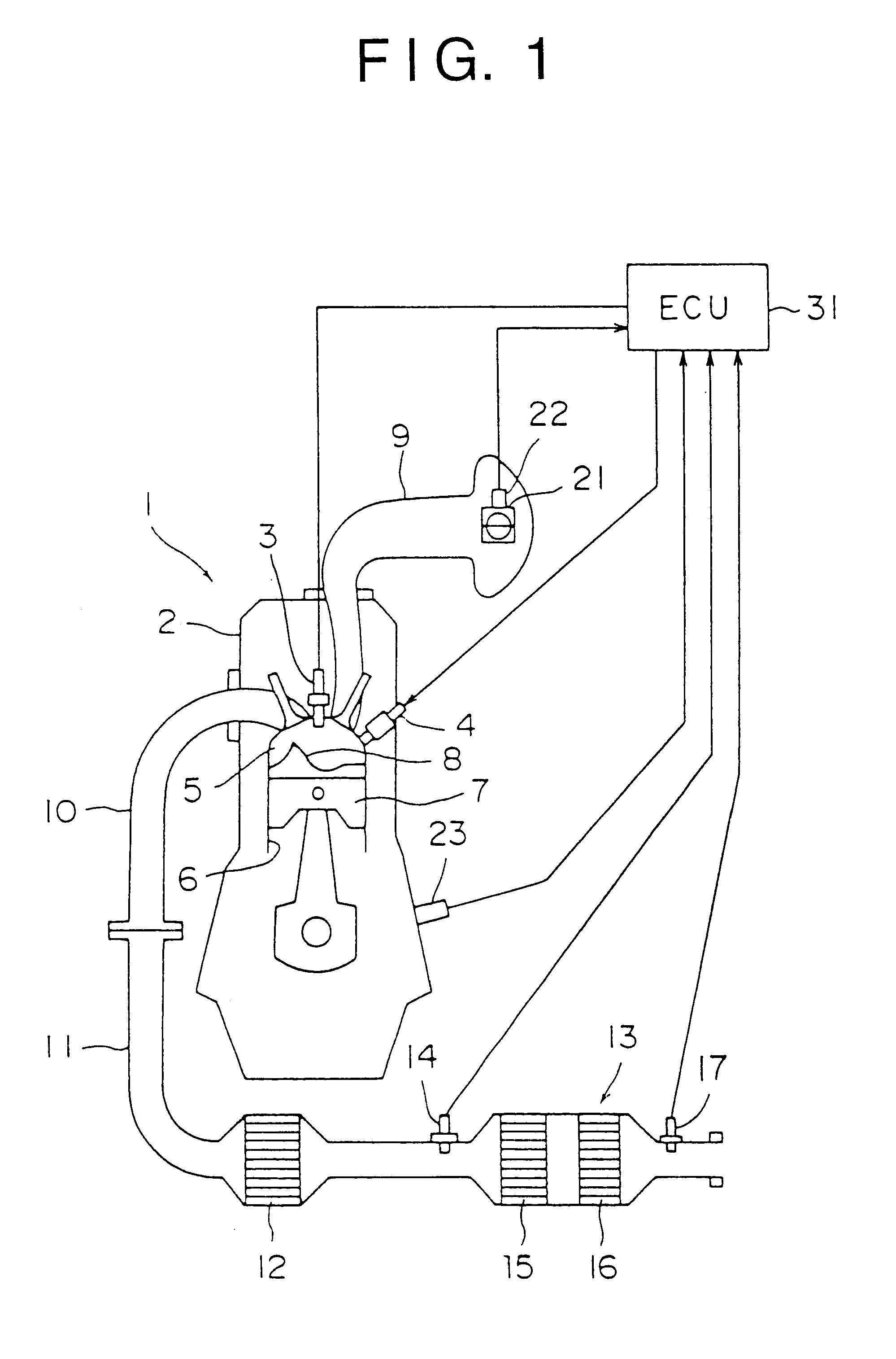
Embodiments of the present invention will next be described in detail with reference to the drawings.

A cylinder-injection-type straight 4-cylinder gasoline engine (cylinder-injection engine) 1 will be described as an example of a multiple-cylinder cylinder-injection-type internal combustion engine. In the cylinder-injection engine 1, fuel injection during an intake stroke (intake-stroke injection mode) or fuel injection during a compression stroke (compression-stroke injection mode) can be performed through, for example, switching of combustion modes (operation modes). The cylinder-injection engine 1 enables operation at a stoichiometric air-fuel ratio (stoichiometry), operation at a rich air-fuel ratio (rich-air-fuel-ratio operation), and operation at a lean air-fuel ratio (lean-air-fuel-ratio operation). Particularly, in the compression-stroke injection mode, the cylinder-injection engine 1 can be operated at an ultra-lean air-fuel ratio, which is greater than the air-fuel ratio o...


PUM


Abstract

When a NOx-releasing unit is operated to change an air-fuel ratio to a rich side to thereby establish a low-oxygen-concentration atmosphere of an exhaust gas such that NOx is released from a NOx catalyst, a reducer-supplying unit 33 additionally supplies a reducer during an operating period of the NOx-releasing unit for reducing NOx released into an exhaust path such that release of NOx balances with reduction of NOx, thereby reducing NOx released from the NOx catalyst and thus suppressing worsening of exhaust gas performance.

Description

1. Field of the InventionThe present invention relates to an exhaust gas purifier for use in an internal combustion engine having, in an exhaust gas passage thereof, a catalyst device (NOx catalyst) which occludes NOx contained in the exhaust gas at a lean air-fuel ratio; i.e., in an oxygen-excessive atmosphere, and which releases occluded NOx at a stoichiometric air-fuel ratio or a rich air-fuel ratio; i.e., in a low-oxygen-concentration atmosphere.2. Description of the Prior ArtRecently, in order to improve fuel economy, a lean-burn engine enabling combustion at a lean air-fuel ratio has been put into practical use. The lean-burn engine has a problem in that a conventional three-way catalytic converter cannot sufficiently purify NOx in an exhaust gas during a lean combustion due to its purification characteristics. Thus, recently there has been employed, for example, a catalyst device (NOx catalyst) for purifying NOx in the exhaust gas during the lean combustion through occlusion ...

Claims


Application Information

Patent Timeline
Patent Type & Authority Patents(United States)
IPC IPC(8): B01D53/94F02D41/02F01N3/08F01N3/20F02D41/40F01N7/02F01N7/00F01N13/02
CPCB01D53/9495F01N3/0814F01N3/0842F01N3/0871F01N3/101F02D41/027F02D41/0275F02D41/405F01N13/009F01N13/0097F01N13/0093F01N2250/12F01N2550/03F01N2570/14F01N2610/03Y02T10/44Y02T10/22Y02T10/12Y02T10/40Y02A50/20
Inventor OKADA, KOJIRONAKAYAMA, OSAMUTAMURA, YASUKIKAWASHIMA, KAZUHITO
Owner MITSUBISHI MOTORS CORP
Why Eureka
Try Eureka