Gas Turbine Combustor

a technology of combustor and gas turbine, which is applied in the direction of machines/engines, combustion types, lighting and heating apparatus, etc., can solve problems such as reliability problems, and achieve the effect of maintaining reliability and stability of combustion in a wide load rang

Inactive Publication Date: 2011-08-04
MITSUBISHI HITACHIPOWER SYST LTD
View PDF9 Cites 22 Cited by
  • Summary
  • Abstract
  • Description
  • Claims
  • Application Information

AI Technical Summary

Benefits of technology

[0027]in each of the multi-coaxial-injection-hole burners, a first part of the fuel nozzles arranged circumferentially and a first part of the air-apertures arranged circumferentially are arranged coaxially so that the fuel nozzles of the first part are for the respective air-apertures of the first part to form a first part of the multi-coaxial-injection-hole burner surrounding the protrusion, a second part of the fuel nozzles arranged circumferentially and a second part of the air-apertures arranged circumferentially are arranged coaxially so that the fuel nozzles of the second part are for the respective air-apertures of the second part to form a second part of the multi-coaxial-injection-hole burner surrounding coaxially the first part of the multi-coaxial-injection-hole burner, a third part of the fuel nozzles arranged circumferentially and a third part of the air-apertures arranged circumferentially are arranged coaxially so that the fuel nozzles of the third part are for the respective air-apertures of the third part to form a third part of the multi-coaxial-injection-hole burner surrounding coaxially the second part of the multi-coaxial-injection-hole burner, a diameter of each of the air-apertures in the first part of the multi-coaxial-injection-hole burner is smaller than a diameter of each of the air-apertures in the second part of the multi-coaxial-injection-hole burner, and a diameter of each of the air-apertures in the second part of the multi-coaxial-injection-hole burner is smaller than a diameter of each of the air-apertures in the third part of the multi-coaxial-injection-hole burner, so that the first part of the multi-coaxial-injection-hole burner keeps a flame of the gas turbine combustor and the second and third parts of the multi-coaxial-injection-hole burner performs low NOx combustion.
[0028]According to the invention, even when a concentration of the hydrogen in the fuel supplied to the gas turbine combustor varies, a change in position of the flame caused by the variation of the concentration of hydrogen is restrained to keep reliability and stability of the combustion in a wide load range, so that the gas turbine combustor capable of keeping the low NOx combustion performance is obtainable.

Problems solved by technology

When the low-calorie gas fuel including hydrogen in a fuel composition is used for the gas turbine combustor, since combustion speed of hydrogen is high, it is highly likely that, when flame formed in the gas turbine combustor approaches the combustor structure, the flame causes a problem in reliability.

Method used


Image

  • Gas Turbine Combustor
  • Gas Turbine Combustor
  • Gas Turbine Combustor

Examples


embodiments

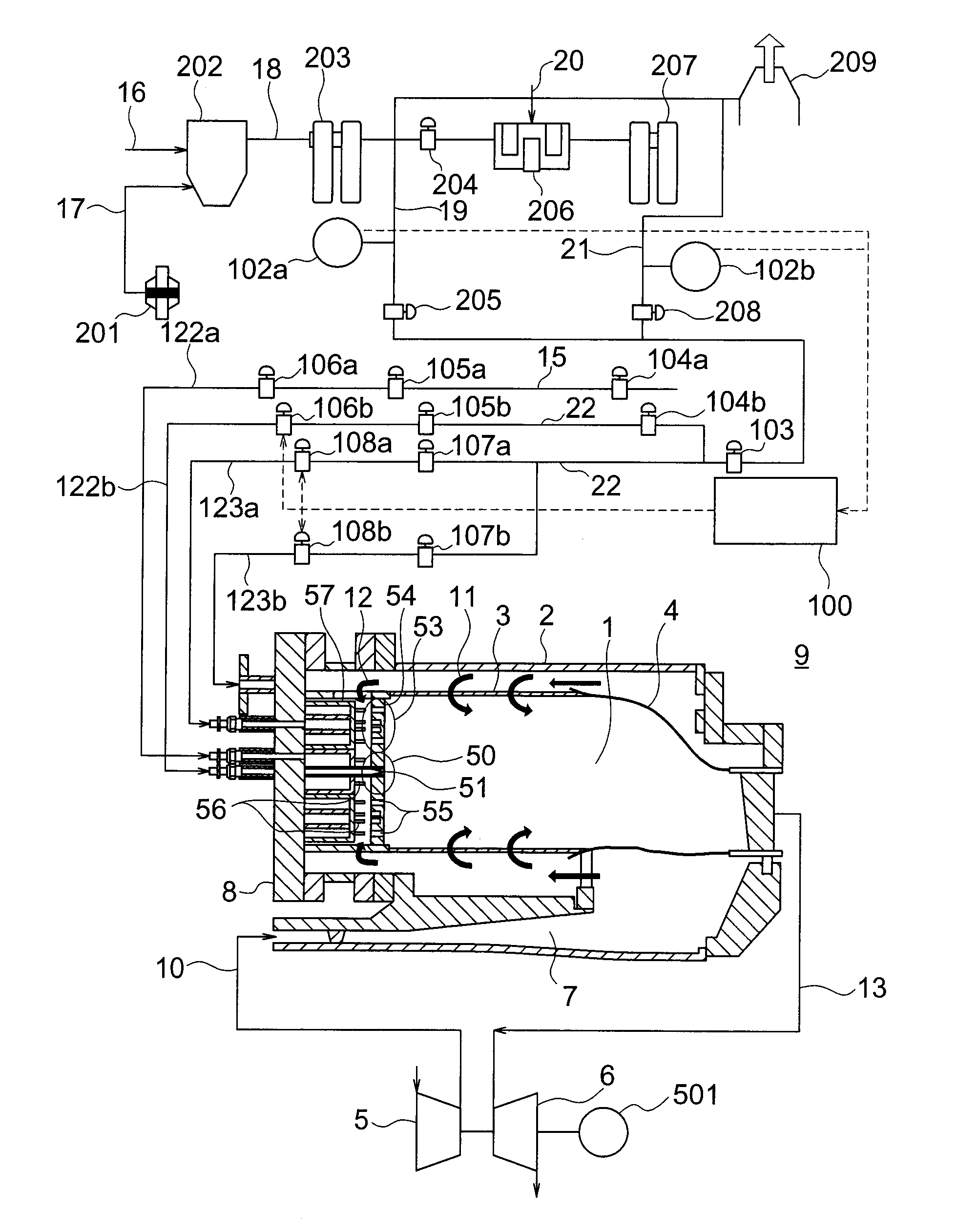
[0047]The gas turbine combustor according to the embodiment of the present invention is explained with reference to FIGS. 1, 2, and 12.

[0048]FIG. 1 is a schematic diagram of a coal gasification combined power generation plant including a gas turbine plant including a gas turbine combustor according to a first embodiment of the present invention.

[0049]The gas turbine combustor according to the present invention may be applied to, besides the coal gasification combined power generation plant explained below, a gas turbine that uses, as fuel, coke oven gas (COG), which is by-product gas obtained from a steel manufacturing plant, blast furnace gas (BFG), or Linzer Donawiz gas (LDG) or mixed gas of these gases and a gas turbine that uses, as fuel, by-product gas obtained from a naphtha cracking plant or the like.

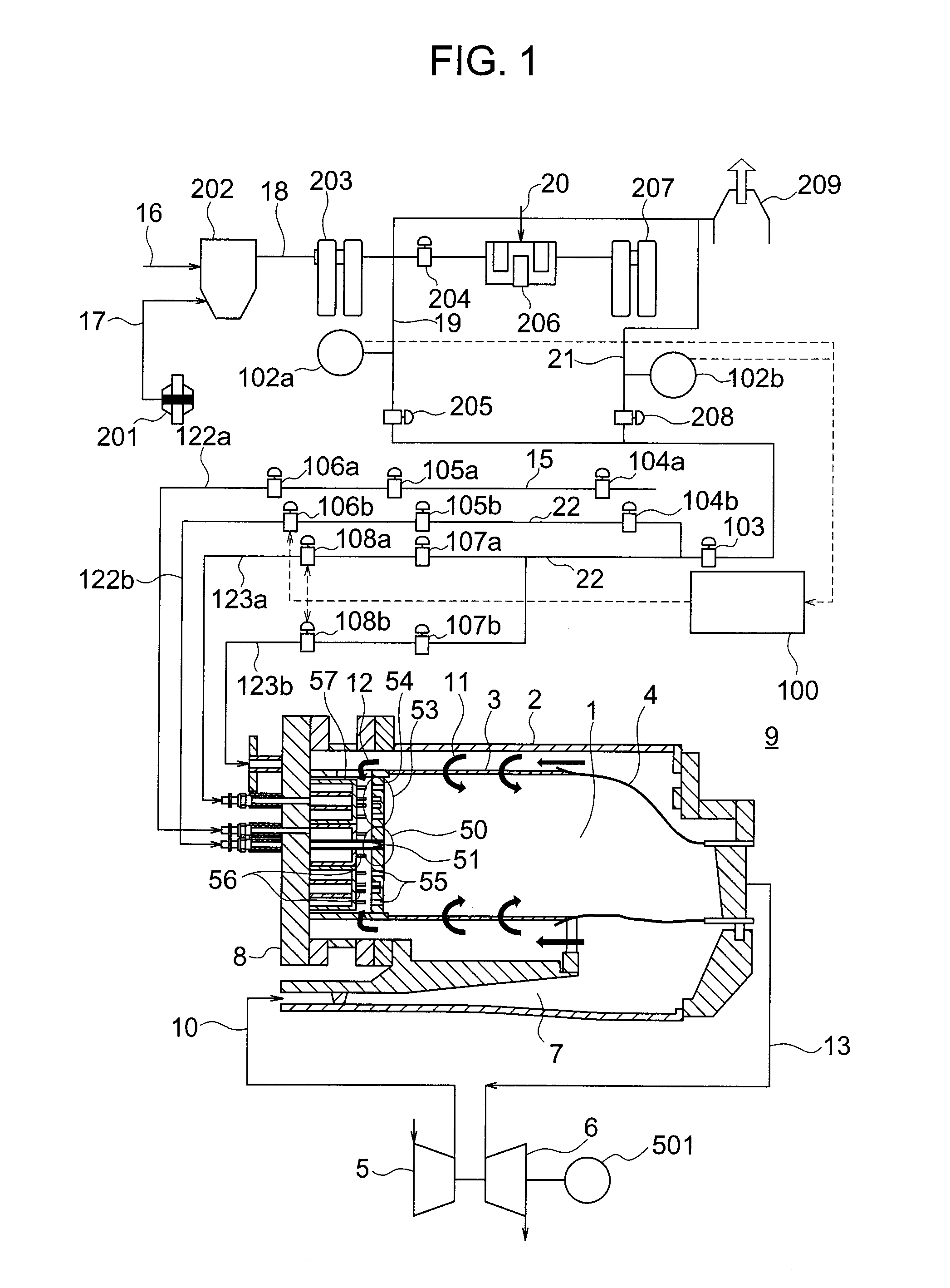
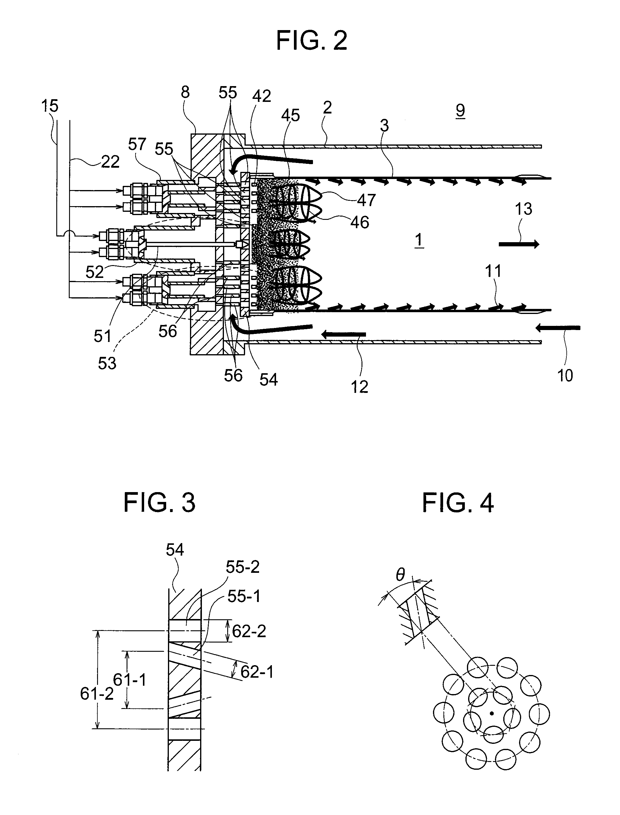
[0050]FIG. 2 is a sectional view showing the schematic structure of the gas turbine combustor according to the first embodiment of the present invention shown in FIG. 1. FIGS. 3 ...


PUM


Abstract

A gas turbine combustor includes plural multi-coaxial-injection-hole burners in which plural fuel nozzles and plural air holes provided in an air plate to correspond to the respective fuel nozzles are coaxially arranged. Each of the multi-coaxial-injection-hole burners includes a first coaxial injection burner disposed on an inner circumferential side, and a second coaxial injection burner disposed on an outer circumferential side, and a diameter of the air holes of the first coaxial injection burner is smaller than a diameter of the air holes of the second coaxial injection burner. Combustion for carrying out flame holding of a gas turbine combustor is performed by the first coaxial injection burner, and low NOx combustion of the gas turbine combustor is performed by the second coaxial injection burner.

Description

[0001]The present invention relates to a gas turbine combustor including a plurality of coaxial nozzles.[0002]As one of power generation plants that support industrial electric power, there is a gas turbine power generation plant that uses fossil resources such as natural gas and petroleum as fuel. Since the gas turbine power generation plant uses the fossil resources as the fuel and emits carbon dioxide (CO2), which is a global warming substance, further improvement of power generation efficiency is demanded.[0003]Examples of means for improving the power generation efficiency include an increase in temperature of combustion gas emitted from a gas turbine combustor.[0004]However, according to the increase in temperature of the combustion gas, nitrogen oxides (NOx), which is an environment inhibiting substance, included in the combustion gas exponentially increases. Therefore, a measure for reducing NOx while improving the power generation efficiency is an important technical object...

Claims


Application Information

Patent Timeline
Patent Type & Authority Applications(United States)
IPC IPC(8): F23R3/28F02C7/228
CPCF23D14/24F23R3/12Y02E20/16F23R3/34F23R2900/00002F23R3/286Y02E20/18
Inventor DODO, SATOSHIKOIZUMI, HIROMITAKAHASHI, HIROKAZUASAI, TOMOHIROMIURA, KEISUKE
Owner MITSUBISHI HITACHIPOWER SYST LTD
Why Eureka
Try Eureka