Fuel injection valve, combustor using the fuel injection valve, and fuel injection method for the fuel injection valve

Inactive Publication Date: 2009-02-05
IHI CORP
View PDF16 Cites 8 Cited by
  • Summary
  • Abstract
  • Description
  • Claims
  • Application Information

AI Technical Summary

Benefits of technology

[0027]In accordance with the structure in accordance with the present invention mentioned above, since the structure is made such that a strong whirl flow is formed by injecting the air to the inner side in the tangential direction from the air injection port provided in the injection valve main body, and the fuel is injected to the outer side, that is, the inner peripheral surface of the injection valve main body from the fuel nozzle arranged on the center line of the injection valve main body, the fuel coming into collision with the inner peripheral surface is atomized in a moment of time by the air (the strong whirl flow) injected from the air injection port, and it is possible to rapidly mix the fuel. Accordingly, it is possible to effectively prevent the flashback, the self-ignition and the oscillated combustion from being generated without necessity of the provision of the premixing portion such as the conventional premixing type fuel injection valve, and it is possible to achieve the low NOx combustion.
[0054]Therefore, it is possible to essentially prevent the flashback, the self-ignition and the oscillated combustion on the basis of the flame-out action caused by the flame expansion generated in the mixed region, and it is possible to achieve the low NOx generation.

Problems solved by technology

In this case, if the concentration of the fuel gas becomes lean, it becomes hard to ignite the fuel gas.
However, in the lean premixing combustion type low NOx combustor, there is a problem that it is hard to stably burn the lean fuel gas, and a flashback or an oscillated combustion tend to be generated.
There is a problem that in spite that the low NOx can be obtained in accordance with the lean premixing combustion, a CO concentration tends to become higher due to a low flame temperature.
However, in the conventional premixing combustion type combustor mentioned above, there is a problem that the flashback, a self-ignition or a combustion oscillation is generated.
However, since the premixing portion (the pre-evaporation premixing pipe 59b) mixing the air and the fuel, and the combustion region are directly connected by the flow path of the premixed gas, there is a problem that the flame in the combustion region flashes back into the premixing flow path in the case that the flow rate of the premixed gas flowing in the premixing flow path is slower than the combustion speed.
Further, even if the flashback is not generated, there is a problem that the premixed gas self ignites within the premixing flow path under a condition that the inlet of the combustor becomes a high temperature and a high pressure.
Further, there is a problem that the combustion oscillation is generated if a periodic pressure fluctuation is generated within the combustor on the basis of the combustion, and a phase of a fluctuation of a heat generation amount within the combustor caused by the pressure fluctuation comes into line with a certain condition.
If the combustion oscillation is generated, a high cycle oscillation and a noise are generated due to the periodic fluctuation of the pressure of the combustor, as well as a fluctuation width of the combustion pressure is amplified and the combustion becomes unstable.
For example, since the ignition of the premixed gas injected into the combustor does not become stable in the case that the pilot flame becomes unstable, the combustion state of the injected premixed gas is fluctuated.
The generation of the flashback, the self-ignition and the combustion oscillation in the low NOx combustor may come to such a severe problem as to cause a burnout of the combustor in some cases.
Accordingly, since a compressor ratio of a compressor and a combustor inlet temperature is increased in an aircraft engine, the risk is further increased, thereby generating an obstacle at a time of applying the low NOx combustor provided with the premixing type fuel injection valve to the aircraft engine.

Method used


Image

  • Fuel injection valve, combustor using the fuel injection valve, and fuel injection method for the fuel injection valve
  • Fuel injection valve, combustor using the fuel injection valve, and fuel injection method for the fuel injection valve
  • Fuel injection valve, combustor using the fuel injection valve, and fuel injection method for the fuel injection valve

Examples


Embodiment Construction

[0065]A description will be in detail given below of preferable embodiments in accordance with the present invention with reference to the accompanying drawings. In this case, the same reference numerals are attached to the portions which are in common in the drawings, and an overlapping description will be omitted.

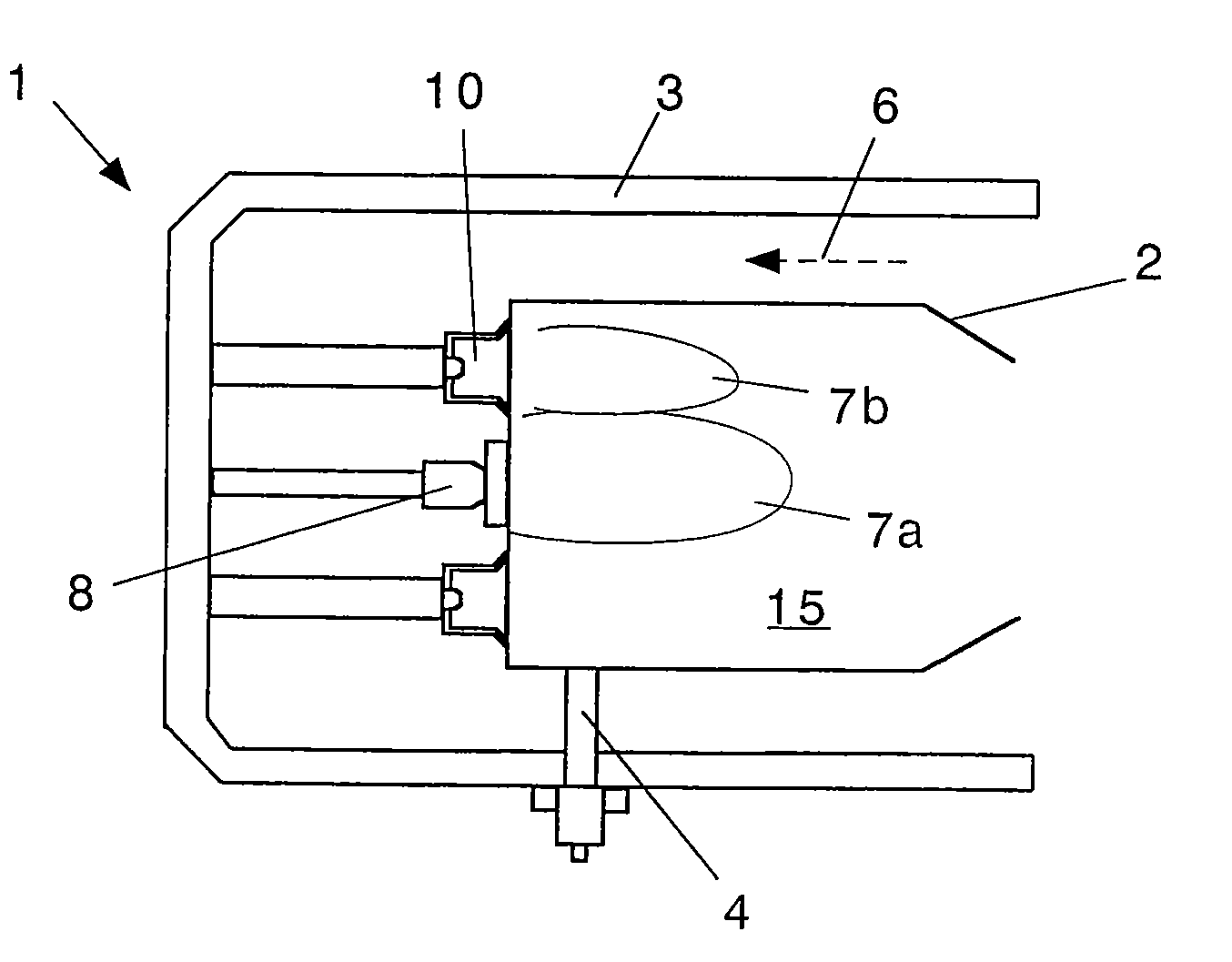
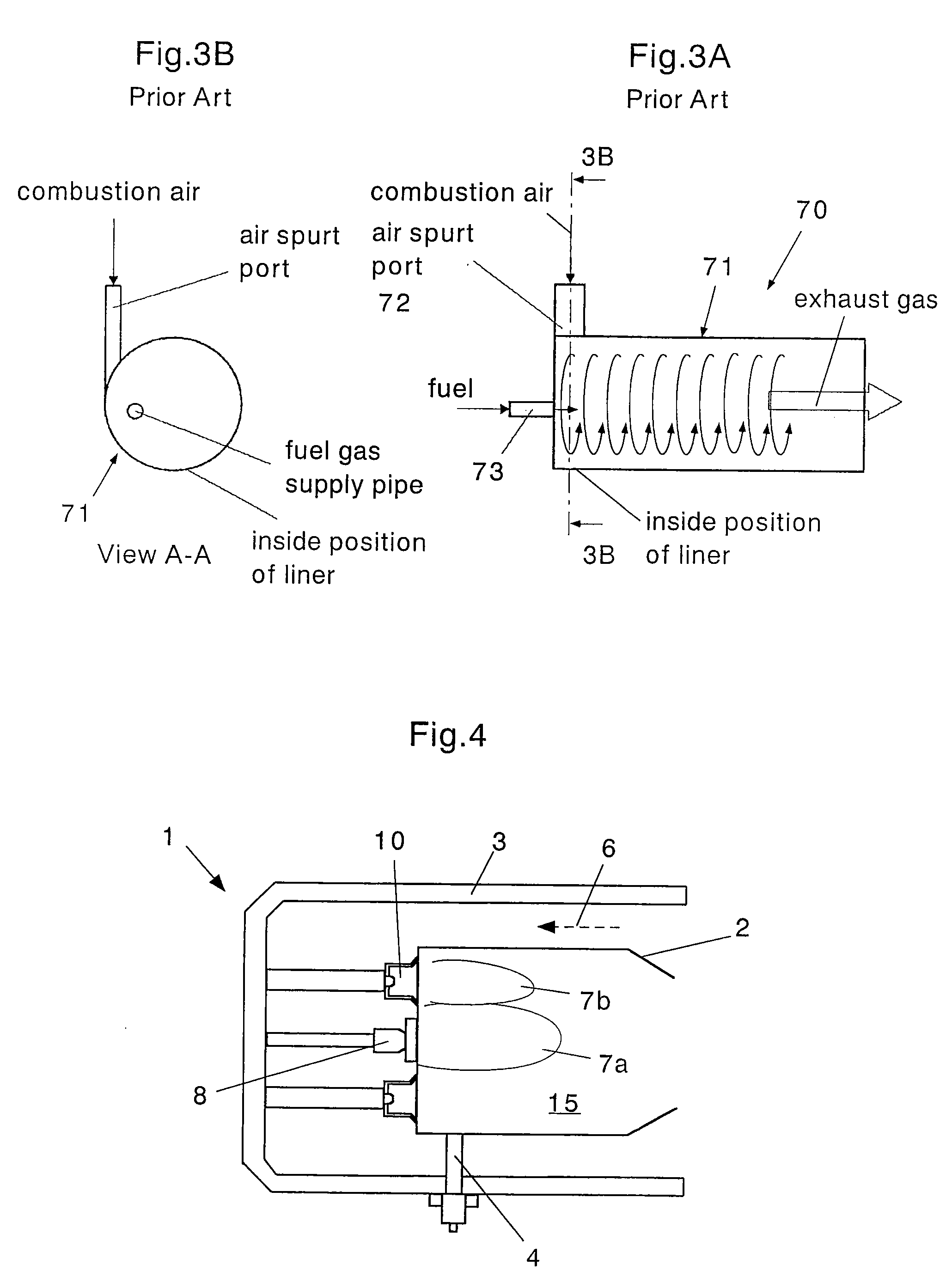
[0066]FIG. 4 is a schematic view of a whole structure of a combustor provided with a fuel injection valve in accordance with the present invention. A combustor 1 shown in FIG. 4 is provided with a pilot burner 8 arranged in an upstream side and a center portion of a combustion chamber 15, and a plurality of (for example, six) fuel injection valves 10 (main burners) arranged on a concentric circle of the pilot burner. In this case, in the drawing, reference numeral 2 denotes a combustor liner, reference numeral 3 denotes a casing, and reference numeral 4 denotes an ignition plug (an igniter). In accordance with the structure, an air 6 flows between the casing 3 and the lin...


PUM


Abstract

A fuel injection valve is provided with a cylindrical injection valve main body in which one end is closed, and a fuel nozzle arranged on a center line of the main body and injecting a fuel. The main body has a plurality of air injection ports for injecting an air to an inner side in a tangential direction and forming a whirl flow in an inner portion in a circumferential direction of a cylinder portion of the main body, and the fuel nozzle has a fuel injection port injecting the fuel toward an inner peripheral surface of the main body.

Description

BACKGROUND OF THE INVENTION[0001]1. Technical Field of the Invention[0002]The present invention relates to a fuel injection valve used in a combustor such as a gas turbine or the like, a combustor using the same, and a fuel injection method thereof.[0003]2. Description of the Related Art[0004]For an environmental protection, it is made compulsory to reduce a nitrogen oxide (NOx) in a combustion exhaust gas of a gas turbine. In our country, it is necessary to make it, for example, equal to or less than 70 ppm in a national standard, and for example, equal to or less than 25 to 30 ppm in a large city (for example, in Tokyo).[0005]A cause that the NOx is generated is mainly constituted by a so-called thermal NOx that a nitrogen in an air is oxidized due to a high-temperature flame at a time of combustion. In order to reduce the thermal NOx, it is effective to reduce a hot spot in the flame, and inhibit the high-temperature flame from being generated. Accordingly, there has been convent...

Claims


Application Information

Patent Timeline
IPC IPC(8): F02C1/00
CPCF02C7/232Y02T50/675F23R3/28F23R3/12Y02T50/60
Inventor HOSOI, JUNHIROMITSU, NAGAYOSHIYOSHIDA, TOMOAKI
Owner IHI CORP
Why Eureka
Try Eureka