Gas turbine combustor

a combustor and gas turbine technology, applied in continuous combustion chambers, combustion processes, lighting and heating apparatus, etc., can solve the problems of increased nox emission, increased possibility of flashback (flame unexpectedly flowing back to the premixer), etc., and achieve the effect of stable combustion

Active Publication Date: 2018-08-28
MITSUBISHI POWER LTD
View PDF30 Cites 0 Cited by
  • Summary
  • Abstract
  • Description
  • Claims
  • Application Information

AI Technical Summary

Benefits of technology

[0012]According to the present invention, it becomes possible to achieve both stable combustion in the central part of the burner and low NOx combustion in the peripheral part of the burner.

Problems solved by technology

In this case, however, there is an apprehension that the amount of NOx emission increases with the increase in the flame temperature in the gas turbine combustor.
However, the possibility of flashback (flame unexpectedly flowing back to the premixer) increases since the combustion speed increases with the increase in the air temperature or in the hydrogen content in the fuel.

Method used


Image

  • Gas turbine combustor
  • Gas turbine combustor
  • Gas turbine combustor

Examples


first embodiment

(1) First Embodiment

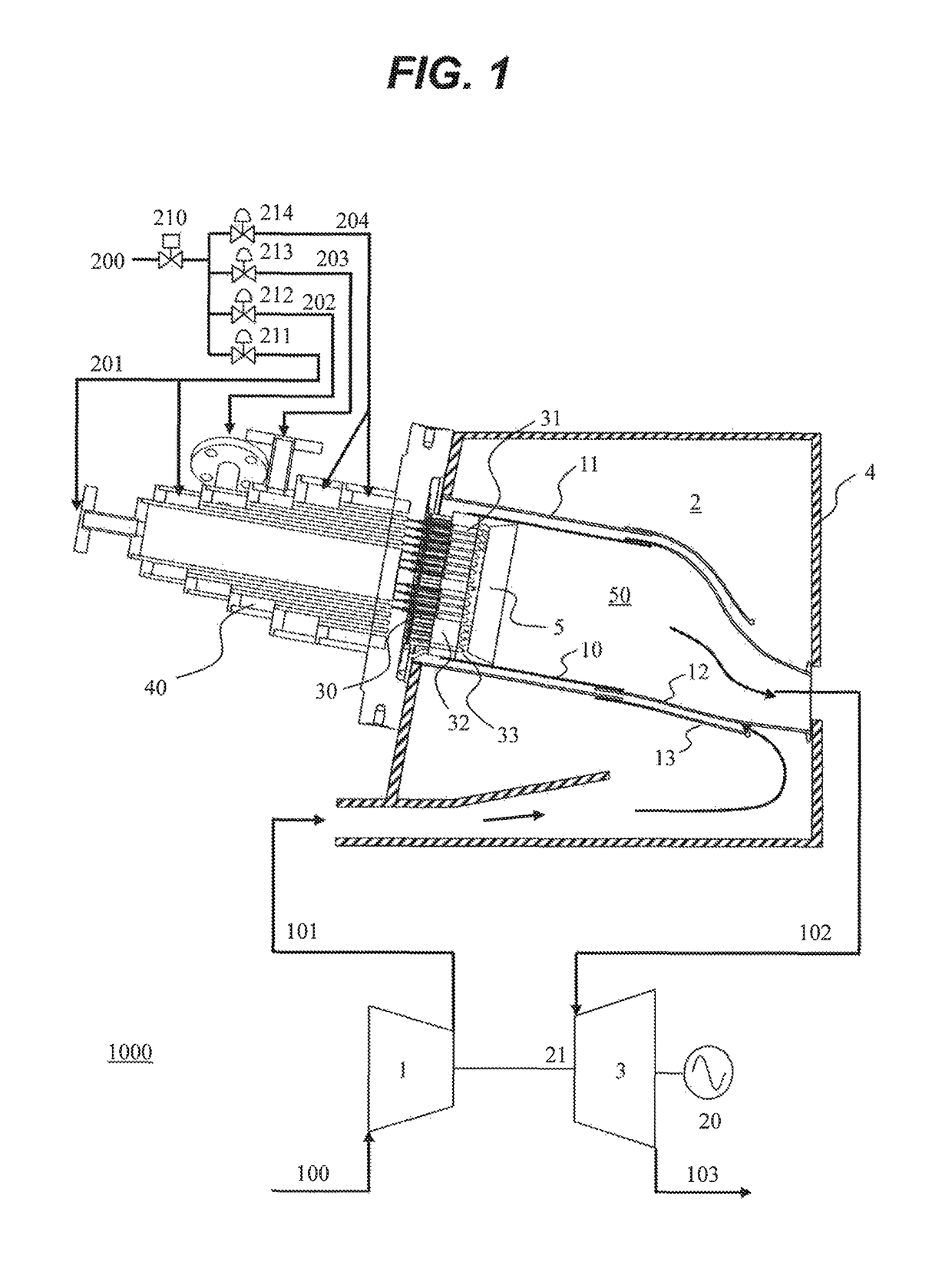
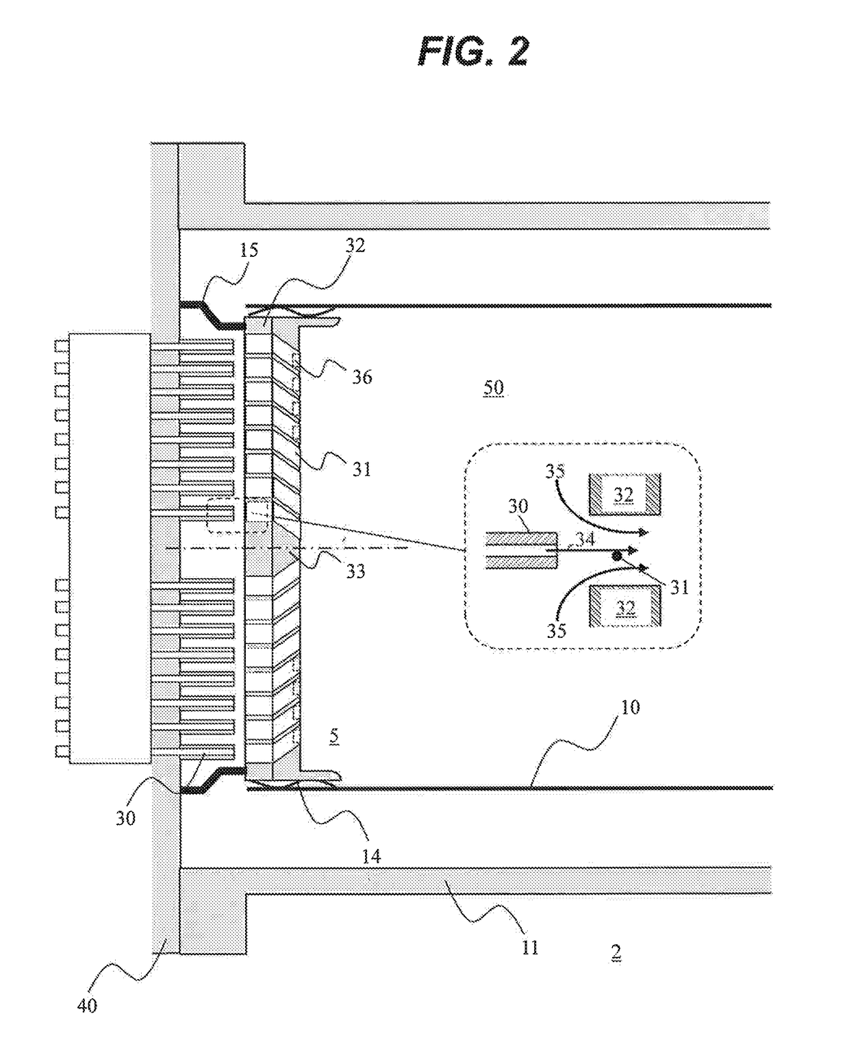
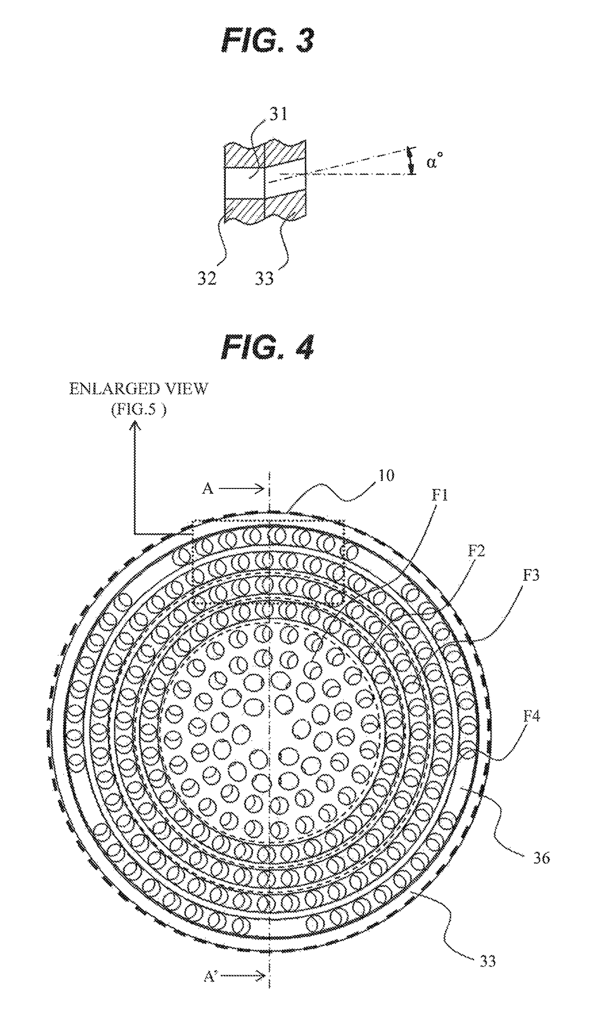
[0037]First, a gas turbine plant comprising a gas turbine combustor in accordance with a first embodiment of the present invention will be descried below by referring to FIG. 1. The gas turbine combustor in accordance with the first embodiment of the present invention comprises: multiple burners which mix fuel and air together and inject the air-fuel mixture into a combustion chamber to cause combustion; a fuel header in which a plurality of fuel nozzles for discharging the fuel are arranged; an air hole plate formed with a plurality of air holes for mixing the fuel and the air together and injecting the air-fuel mixture into the combustion chamber are formed; and a plurality of air-fuel coaxial jets formed by coaxially arranging the fuel nozzles and the air holes. Grooves in which part of the unburned premixed gas supplied from the air holes to the combustion chamber flows are formed downstream of the air holes. The thickness of a remaining wall between the groo...

second embodiment

(2) Second Embodiment

[0074]Next, a gas turbine combustor in accordance with a second embodiment of the present invention will be described below. The basic configuration of the gas turbine and the gas turbine combustor according to this embodiment is equivalent to that in the first embodiment shown in FIGS. 1-8. Therefore, the following explanation will be given mainly of the difference from the first embodiment while omitting explanation of the configuration and effects common to the first and second embodiments. The method of operating the combustor 2 in this embodiment is substantially equivalent to that in the first embodiment explained referring to FIG. 8 and thus repeated explanation thereof is omitted for brevity.

[0075]FIG. 9 is a schematic diagram of the air hole plates (the base plate 32 and the swirl plate 33) in the second embodiment of the present invention viewed from the downstream side. This embodiment differs from the first embodiment in that the hole diameter of the...

third embodiment

(3) Third Embodiment

[0083]Next, a gas turbine combustor in accordance with a third embodiment of the present invention will be described below. The basic configuration of the gas turbine and the gas turbine combustor according to this embodiment is also equivalent to that in the first embodiment shown in FIGS. 1-8, and thus the following explanation will be given mainly of the difference from the first embodiment. The method of operating the combustor of the gas turbine plant in this embodiment is also substantially equivalent to that in the first embodiment of the present invention and thus repeated explanation thereof is omitted for brevity.

[0084]FIG. 14 is a schematic diagram of the air hole plates (the base plate 32 and the swirl plate 33) in the third embodiment of the present invention viewed from the downstream side.

[0085]The grooves 36 formed in the F2, F3 and F4 burners in this embodiment differ from those in the prior two embodiments in that each groove 36 in this embodime...


PUM


Abstract

In a perforated coaxial jet burner implemented by a lot of air-fuel coaxial jets, a swirl plate (33) as an end face of the burner on the combustion chamber's side has a lot of air holes for supplying unburned premixed gas of fuel and air to the combustion chamber. Grooves (36) are formed downstream of the air holes of the swirl plate. Adhesion of flame to the swirl plate is inhibited by feeding part of the unburned premixed gas to the grooves. Further, the width of each remaining part (37) between adjacent grooves is set at several millimeters that is approximately equal to the flame quenching distance, by which adhesion of flame to the remaining parts is also prevented. With this configuration, both stable combustion and low NOx combustion can be achieved irrespective of the load condition.

Description

TECHNICAL FIELD[0001]The present invention relates to a gas turbine combustor.BACKGROUND ART[0002]Regulations and social demands for environmental conservation are intensifying day by day and still further efficiency improvement and NOx reduction are being required today also in the field of gas turbines. As a method for increasing the efficiency of a gas turbine, it is possible to increase the gas temperature at the inlet of the turbine. In this case, however, there is an apprehension that the amount of NOx emission increases with the increase in the flame temperature in the gas turbine combustor.[0003]There exist gas turbine combustors employing premix combustion in order to reduce the NOx emission. The premix combustion is a combustion method in which air-fuel mixture obtained by previously mixing fuel and air together (premixed gas) is supplied to the gas turbine combustor and burned. Such a gas turbine combustor employing the premix combustion comprises a burner which has a pre...

Claims


Application Information

Patent Timeline
Patent Type & Authority Patents(United States)
IPC IPC(8): F23R3/12F23R3/32F23R3/30F23R3/28F23R3/34
CPCF23R3/12F23R3/28F23R3/286F23R3/346F23R3/32F23R3/343F23R3/30
Inventor ABE, KAZUKIKOGANEZAWA, TOMOMIMIURA, KEISUKE
Owner MITSUBISHI POWER LTD
Why Eureka
Try Eureka