Fuel Injection System of Internal Combustion Engine

a fuel injection system and internal combustion engine technology, applied in the direction of liquid fuel feeders, machines/engines, electric control, etc., can solve the problems of low actual injection pressure at the time of after injection, and insufficient reduction of emissions matched with engine operating conditions, so as to reduce emissions, reduce emissions, and reduce production

Inactive Publication Date: 2008-03-06
TOYOTA JIDOSHA KK
View PDF4 Cites 24 Cited by
  • Summary
  • Abstract
  • Description
  • Claims
  • Application Information

AI Technical Summary

Benefits of technology

[0008] An object of the present invention is to provide a fuel injection system which deliberately uses after injection to improve engine combustion and reduce soot and NOx. Further, it has as its object to provide a fuel injection system enabling also initial injection for reducing the noise due to ignition lag or NOx.
[0009] In view of this situation, the inventors searched for ways to deliberately utilize after injection for engine combustion and repeatedly conducted experiments and simulations. As a result, they discovered that by deliberately using after injection under certain conditions, it is possible to remarkably improve the engine combustion performance, reduce the soot and NOx, and greatly enhance the output.

Problems solved by technology

However, in the fuel injection system described in Japanese Patent Publication (A) No. 2002-322957, the tip of the needle valve ejected the fuel for the after injection, so the actual injection pressure at the time of after injection was low.
Even after performing after injection for a certain period, the soot produced at the time of the main injection could not be burned off and the NOx could not be deoxidized, so the emissions could not be sufficient reduced.
Further, in this fuel injection system, the after injection period could not be freely controlled, so emissions could not be sufficiently reduced matched with the engine operating conditions.
Further, in this fuel injection system, initial injection was not possible, so there were the problems of combustion noise due to the ignition lag and the inability to reduce the rapid rise of pressure in the cylinder.
Further, in the fuel injection system described in Japanese Patent Publication (A) No. 11-182311, after injection could not be performed consecutively after main injection or the actual injection pressure at the time of after injection was insufficient, so emissions could not be sufficiently reduced.
Further, in this fuel injection system, there was the problem that main injection could not be performed consecutively after the initial injection.
Further, if adding after injection, the total injection period increases, so there was also cause for concern that the combustion period would increase and the cylinder cycle efficiency would deteriorate.
Still, there has been insufficient use of after injection for engine cylinder combustion.

Method used


Image

  • Fuel Injection System of Internal Combustion Engine
  • Fuel Injection System of Internal Combustion Engine
  • Fuel Injection System of Internal Combustion Engine

Examples


first embodiment

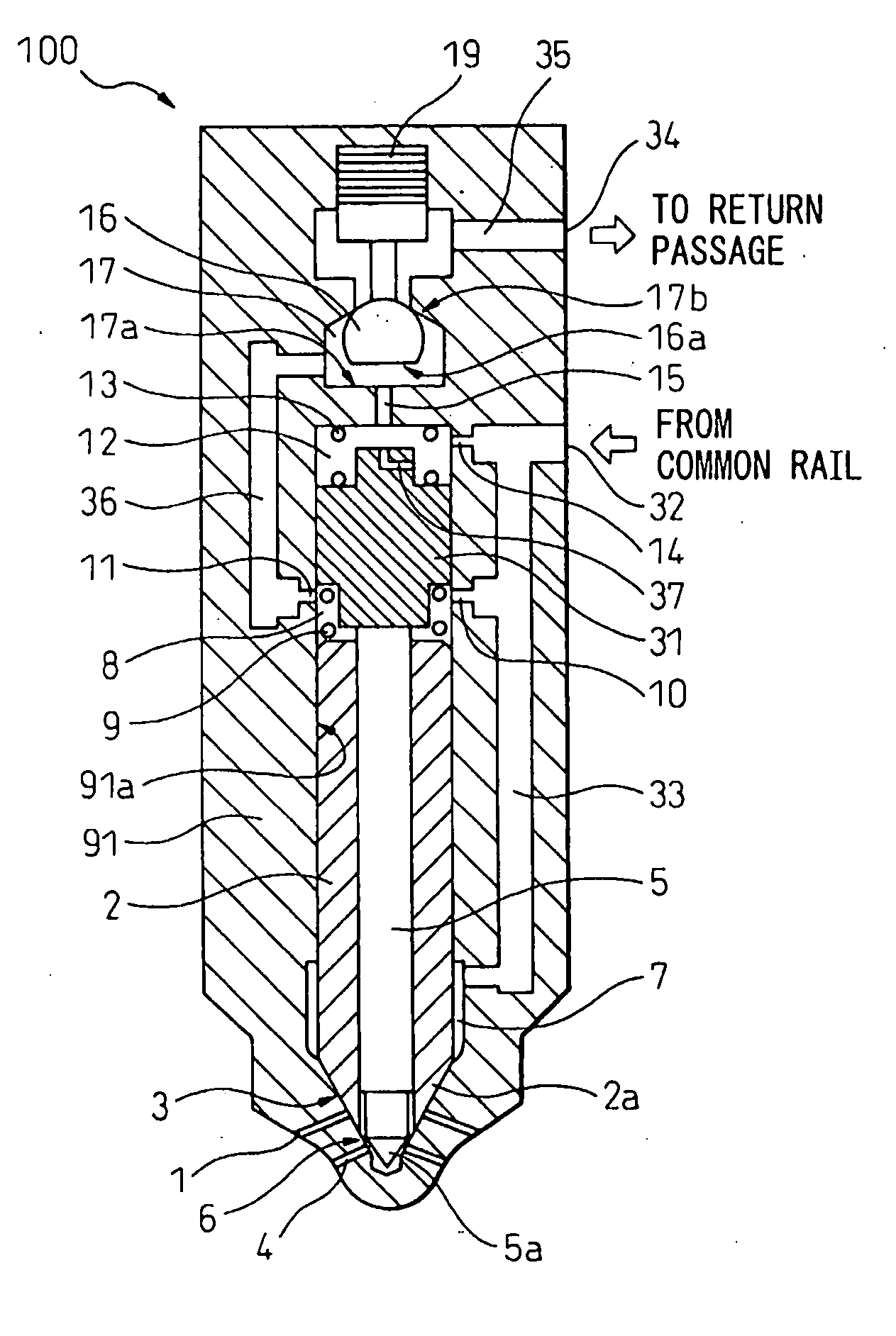
[0069]FIG. 4 is a cross-sectional view of a first embodiment of the fuel injection system according to the present invention. At the time of noninjection when fuel is not injected as shown in FIG. 4, the amounts of lift of the injection port operating valves constituted by the first needle valve and the second needle valve become zero. In FIG. 4, 1 indicates first injection ports from which fuel is injected at the time of initial injection, main injection, and after injection, 2 indicates the first needle valve for opening / closing the first injection ports 1, and 3 is a first seat part where the first needle valve 2 is seated at the time the first needle valve 2 closes the ports. Reference numeral 4 indicates second injection ports from which fuel is injected at the time of main injection, 5 indicates a second needle valve arranged at the inside of the first needle valve 2 for opening / closing the second injection ports 4, 6 indicates a second seat part where the second needle valve ...

second embodiment

[0091] Next, a second embodiment of the fuel injection system according to the present invention will be explained. FIG. 9 is a sectional view of the second embodiment of the fuel injection system according to the present invention and is similar to FIG. 4 according to the first embodiment. The second embodiment basically differs from the first embodiment in that the lift lock piston is eliminated. The method of operation is the same as the first embodiment. As shown in FIG. 9, the cylinder part 91a of the valve body 91 is connected with the smaller inside diameter cylinder part 91b at the top side of the valve body. The second needle valve 5 is arranged to be able to freely slide inside the cylinder part 91b guided by the first needle valve 2.

[0092] The second embodiment, compared with the first embodiment, omits the lift lock piston, so is simplified in structure. The second control chamber 12 is small in inside diameter, so the fuel pressure of the second control chamber 12 caus...

third embodiment

[0093] Below, a third embodiment of the fuel injection system according to the present invention will be explained. FIG. 10 is a sectional view of the third embodiment of the fuel injection system according to the present invention and is similar to FIG. 4 according to the first embodiment. In the same way as in FIG. 4, this shows a noninjection state where the lift of the pressure control valve 16 is made zero and fuel is not injected. Note that in the first embodiment to the third embodiment, compared with the later explained fourth embodiment or fifth embodiment, at the time of start of the initial injection, the first injection ports open, then the second injection ports open, while at the time of start of after injection, the second injection ports close, then the first injection ports close. The third embodiment differs in basic structure from the first embodiment in that the control valve is a two-position valve, the position of the second outlet orifice is a separate positio...


PUM


Abstract

A fuel injection system deliberately utilizing after injection so as to improve the engine combustion and reduce soot and NOx, wherein at least one operating valve is provided for operating a first injection port group and second injection port group, after injection is performed consecutively after main injection in a high load region, fuel is injected from the first injection port group and second injection port group at the time of main injection, fuel is injected from the first injection port group at the time of after injection, the actual injection pressure near the first injection port during the after injection period is higher than the actual injection pressure near the first injection port during the main injection period, the operating valve opens the first injection port group to start the injection, then the operating valve opens the second injection port group simultaneously or in a short time as well to perform the main injection, the operating valve closes the second injection port group, then performs the after injection, and the operating valve closes the first injection port group and ends the injection after the elapse of a time longer than simultaneously or a short time from after start of after injection.

Description

BACKGROUND OF THE INVENTION [0001] 1. Field of the Invention [0002] The present invention relates to a fuel injection system of an internal combustion engine (below, “engine”). [0003] 2. Description of the Related Art [0004] In the past, there has been known a common rail type fuel injection system performing “after injection” following “main injection”. As an example of this type of fuel injection system, for example, there is the one described in Japanese Patent Publication (A) No. 2002-322957. In the fuel injection system described in Japanese Patent Publication (A) No. 2002-322957, after injection can be performed to reduce emissions. Japanese Patent Publication (A) No. 2003-254188 describes an injection rate-mode similar to after injection in FIG. 11 and Paragraph No. [0055], but does not describe the content in detail. Japanese Patent Publication (A) No. 11-182311 describes a common rail type fuel injection system performing separate after injection after main injection. Japan...

Claims


Application Information

Patent Timeline
Patent Type & Authority Applications(United States)
IPC IPC(8): F02M69/46
CPCF02D41/2096F02D41/405F02M45/08F02M45/086F02M47/027Y02T10/44F02M61/161F02M61/182F02M63/0043F02M63/0045F02M2200/46F02M61/042Y02T10/40
Inventor FUTONAGANE, YOSHINORIWATANABE, YOSHIMASASEGUCHI, KAZUHIKO
Owner TOYOTA JIDOSHA KK
Why Eureka
Try Eureka