
Foam support for line pipe

Inactive Publication Date: 2010-05-06
FEATHERBLOCK DESIGN
View PDF18 Cites 27 Cited by
  • Summary
  • Abstract
  • Description
  • Claims
  • Application Information

AI Technical Summary

Benefits of technology

[0007]The present invention provides for a solution to support line pipe in a much easier and concise manner than previously existed. Instead of filling sand bags or forming a pipe support on site by foaming in place, the present invention includes providing a profiled block of foam cut to form a support (also called a “foam block support” herein) that can be snapped onto the line pipe at any interval and then manipulated to a bottom-facing use position on the line pipe, such as one being at or near a longitudinal center of the pipe and others being along the line pipe at various spaced locations, such as at a distance of about 2 to 3 feet from the welded joints at ends of pipe sections. Since the design of the profile is consistent for each piece, the pipe will be inserted within the trench in a manner that allows the foam block to control the height of the pipe within the trench in a consistent manner Advantageously, the physical properties of EPS (expanded polystyrene) are such that the profile of the foam block can be made to include two opposing fingers that permit snap-on attachment to the pipe, but that are designed to allow an unskilled operator to place them over the pipe (such as onto a top of the pipe) and then adjust their longitudinal and / or rotational position to avoid incorrect placement or misalignment when the line pipe is placed in the trench. Gravity assists in assembling the supports onto the line pipe and also in rotating the supports to use positions under the line pipe to form a base parallel to the ground (or floor of a trench). Testing shows that the physical properties of EPS foam material are such that the present foam block supports readily support a weight of the line pipe, and are not adversely deformed by the weight.

Problems solved by technology

The pipe sections are extremely long, as much as 40′ (feet) per section, and since they are often constructed in difficult / remote locations, it is virtually impossible to make the floor of the trench perfectly flat and stable.
Thus, when the pipe is set down on this floor, the construction engineers are not absolutely sure that the pipe is evenly supported.
This can be a problem since uneven support can lead to stress and damage to the line pipe, including both immediate damage and also delayed damage that takes awhile before it results in leakage.
Such leakages are extremely expensive and difficult to repair in the field.
Another problem occurs if the line pipe contacts a hard object that causes damage to the pipe (potentially undetected damage), either during construction or due to movement of earth over time causing the buried object to move against the line pipe.
Thus, the potential problems noted above are still present.
The workers must get into the trench and place the bags accordingly, which is a messy and potentially unsafe position for workers.
Pipe lines are known to extend for hundreds of miles, so this is a costly operation that must be repeated along the entire length of the line.
This method is manually intensive, and further transport of the sand and bags to the construction site is expensive due in part to their weight.
Since there is a certain cure time for the foam, this is a time-consuming process that requires that the pipe be held in a specific location, both horizontally and laterally, for a length of time necessary to cure the foam sufficiently to support the line pipe.
Several operators and an expensive truck equipped to carry and spray foam must travel parallel to the trench along the entire length of the line pipe.
Any mechanical breakdown of either the foam-making equipment or the truck will slow down the process of laying the pipe.
Further, the foaming chemicals, which are potential environmental pollutants, must be transported over difficult terrain.

Method used


Image

  • Foam support for line pipe
  • Foam support for line pipe
  • Foam support for line pipe

Examples


Embodiment Construction

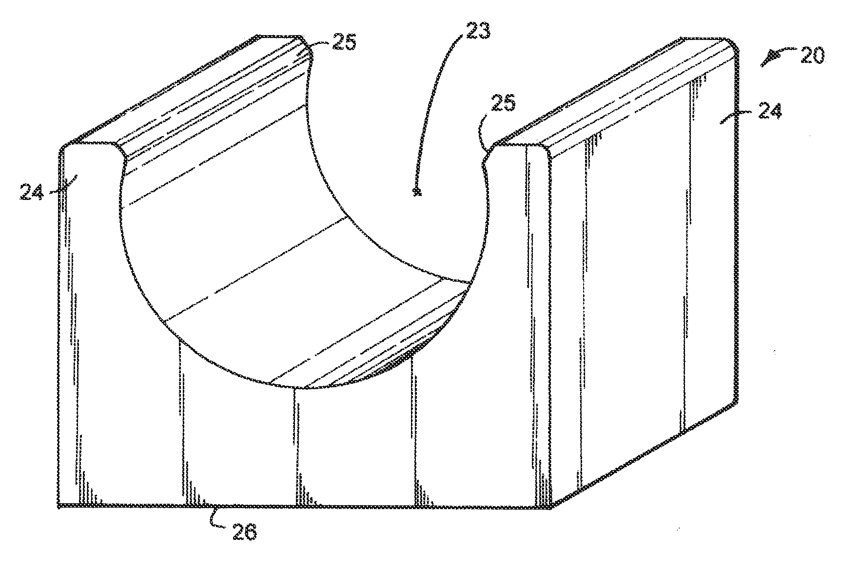
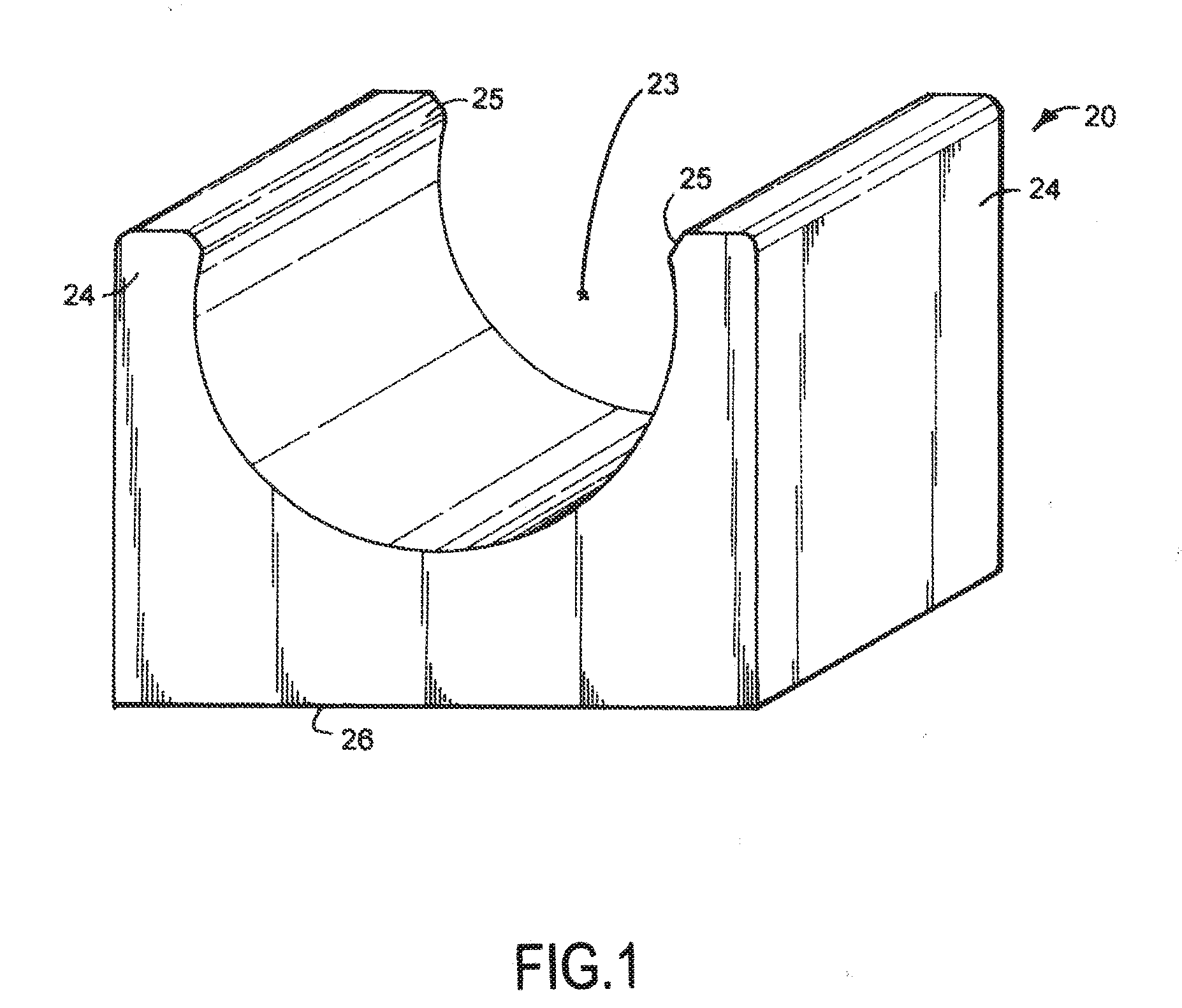
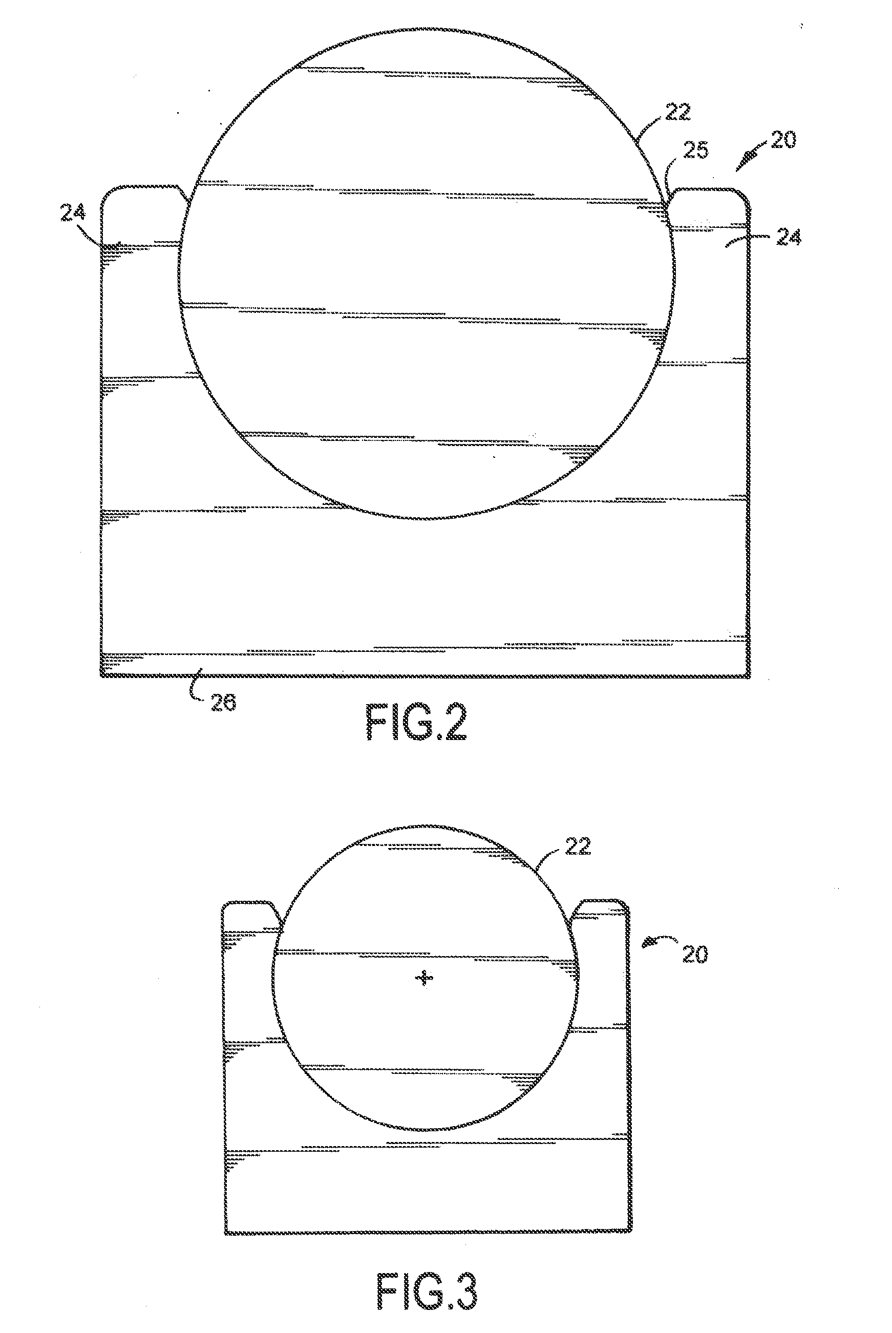
[0030]A series of contoured pipe supports 20 (FIGS. 1-4) made primarily of foam are designed to support line pipe 21 across land or water. Line pipes 21 are commonly made by welding together pipe sections 22, such that the line pipe 21 extends for miles. The supports 20 are configured to snap onto and self-retain to the line pipe 21, are configured to rotate and / or slide to a use position on the pipe 21, and further are configured to resist permanent deformation and to withstand weather conditions. The foam of the supports 20 have sufficient physical and mechanical properties to support the line pipe 21, but the supports 20 are surprisingly lightweight and can be easily installed over pipes 21 for the purpose of supporting and protecting such pipe until the pipe is buried or submerged in the earth. The supports 20 are also sufficiently durable and have sufficient flotation properties to maintain a line pipe 21 in a horizontal position necessary to prevent accidental puncture or leak...


PUM


Abstract

A series of contoured pipe supports made primarily of foam are designed to support line pipe across land or water. The supports are configured to snap onto and self-retain to the line pipe, and further are configured to resist permanent deformation and to withstand weather conditions. The foam of the supports have sufficient physical and mechanical properties to support the line pipe, but the supports are surprisingly lightweight and can be easily installed over pipes for the purpose of supporting and protecting such pipe until the pipe is buried or submerged in the earth. The supports are sufficiently durable and have sufficient flotation to maintain a line pipe in a horizontal position necessary to prevent accidental puncture or leakage of the pipe during assembly and installation.

Description

[0001]This application claims benefit under 35 U.S.C. §119(e) from provisional application Ser. No. 61 / 110,663, filed Nov. 3, 2008, entitled FOAM SUPPORT FOR LINE PIPE.BACKGROUND[0002]The present invention relates to installation of and supports for line pipe, and more particularly relates to supports for line pipe (such as underground pipe lines that extend for long distances) that can be produced at relatively low cost, that are easier and less expensive to install during construction than known systems, and that lead to an improved, more efficient, more robust, and safer installation of line pipe in the field.[0003]Long runs of pipe are made up of multiple sections of pipe welded together (or otherwise secured together) to form a long continuous length, such as for transporting liquids and gases or other semi-liquid materials long distances. This pipe is commonly called “line pipe.” In the case of line pipe that is assembled for use below the ground, a trench is dug to house the ...

Claims


Application Information

Patent Timeline
IPC IPC(8): F16L3/08
CPCF16L1/06F16L3/02
Inventor BROCK, ROBERT D.
Owner FEATHERBLOCK DESIGN
Features
  • Generate Ideas
  • Intellectual Property
  • Life Sciences
  • Materials
  • Tech Scout
  • Unparalleled Data Quality
  • Higher Quality Content
  • 60% Fewer Hallucinations
Learn More