Gripping device and system including the same

a technology of a gripping device and a system, which is applied in the direction of load-engaging elements, metal-working apparatus, joints, etc., can solve the problems of reducing the detection sensitivity of the sensor unit, affecting the sensitivity of the detection axes, so as to reduce the sensitivity difference between the detection axes of the force sensor, the rigidity of the elastic member can be increased, and the rigidity of the elasti

Inactive Publication Date: 2010-05-06
CANON KK
View PDF9 Cites 46 Cited by
  • Summary
  • Abstract
  • Description
  • Claims
  • Application Information

AI Technical Summary

Benefits of technology

[0026]With the above structure, the flexibility in designing rigidities of the displacement axes by combining the elastic materials increases, and desired rigidities can be designed while minimizing the difference in rigidity among the displacement axes (directions). By forming the elastic materials by leaf springs, the rigidity of the elastic member can be increased. Since the sensitivity difference among the detection axes of the force sensors can thus be reduced while increasing the rigidity of the elastic member, accurate force detection is possible.
[0027]According to the present invention, the size of the force sensor units can be reduced while achieving both a high detection sensitivity of the force sensor units and restriction of the increase in stable positioning time during high speed movement of the robotic arm.
[0028]Further, according to the present invention, it is possible to minimize the influence of the moment, which is produced by the inertial force due to the positional difference between the deformation fulcrum of the elastic member and the center of gravity of the grip section, on the force sensor units. Therefore, in particular, the time necessary for stable positioning can be shortened and speedup can be realized.
[0029]In addition, the sensitivity difference among the detection axes of the force sensors can be reduced. Further, when the elastic materials are formed by leaf springs, the rigidity of the elastic member can be increased, and the sensitivity difference among the detection axes of the force sensors can be reduced while increasing the rigidity of the elastic member. This achieves accurate force detection.

Problems solved by technology

Unfortunately, when the rigidity of the elastic members 13 decreases, the grip section G easily wobbles with respect to the robotic arm A. For this reason, during driving of the robotic arm A, it takes much time to stably position the gripping device.
Although the rigidity of the elastic members needs to be increased in order to shorten the time for stable positioning, the increase in rigidity reduces detection sensitivity of the sensor unit, and makes it difficult to accurately detect the force.
In this way, in the gripping device of the related art, when the size of the sensor unit is reduced in the longitudinal direction of the robotic arm, it is difficult to ensure both a high detection sensitivity and a high operation speed.

Method used


Image

  • Gripping device and system including the same
  • Gripping device and system including the same
  • Gripping device and system including the same

Examples


examples

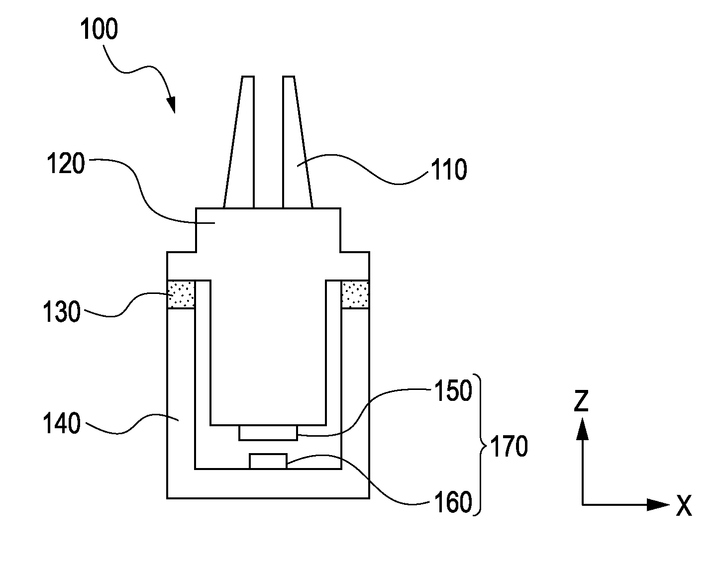
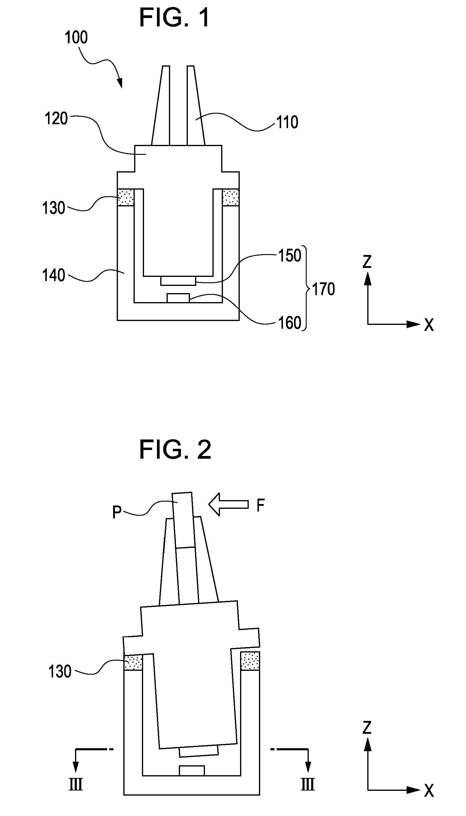
[0047]Referring to FIGS. 1 and 2, a description will be given below of a state in which the gripping device 100 grips and assembles a component P. In FIG. 2, F represents an operating force in an XY plane of an assembly reaction force applied to the fingers 110 when the component P is gripped and assembled. The driving mechanism 120 is displaced relative to the gripping device housing 140 on the elastic member 130, as shown in FIG. 2.

[0048]The force sensor units 170 are defined by a mechanism formed by a combination of a Hall element for detecting the displacement of the driving mechanism 120 relative to the gripping device housing 140, and a permanent magnet serving as a magnetic-field generating source. The mechanism is not particularly limited to the above-described magnetic displacement sensor as long as it can detect the displacement.

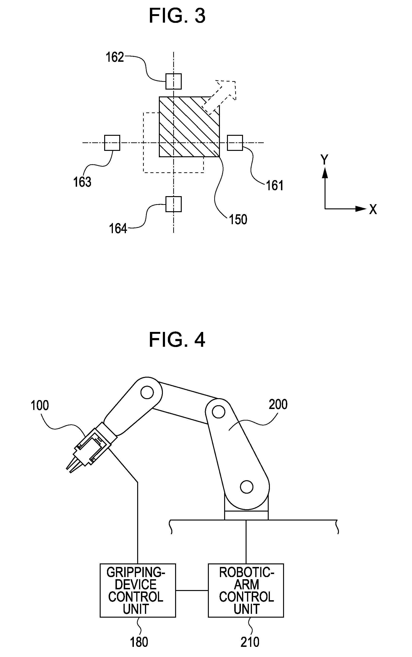
[0049]A calculation unit (not shown) calculates an operating force F from the displacement amount detected by the force sensor units 170. FIG. 3 i...


PUM


Abstract

In a gripping device, a displacement-type force sensor is provided on a side of a driving mechanism opposite fingers to which the driving mechanism is connected to form a grip section. The driving mechanism is supported on a housing with an elastic member being disposed therebetween at a position closer to the fingers than the center of gravity of the grip section.

Description

BACKGROUND OF THE INVENTION[0001]1. Field of the Invention[0002]The present invention relates to a gripping device attached to, for example, a leading end of an arm of an industrial robot so as to grip and assemble various components. More particularly, the present invention relates to a gripping device that detects the assembly reaction force during assembly of components and performs assembly while controlling the assembly force, and that is applicable to automated assembly with an industrial robot.[0003]2. Description of the Related Art[0004]In recent years, there is an increasing demand for automated manufacturing of products having a complicated structure, for example, cameras. For such products, it is necessary to perform high-speed and accurate assembly with a small industrial robot under fine force control.[0005]Japanese Patent Laid-Open No. 61-241083 discloses a technique of controlling a robotic arm and a hand while detecting the assembly force with a displacement sensor p...

Claims


Application Information

Patent Timeline
Patent Type & Authority Applications(United States)
IPC IPC(8): B25J15/00B25J15/02B25J15/08
CPCB23P19/105B25J13/085B25J15/02B25J17/0208Y10T74/20335
Inventor MEISHO, KEN
Owner CANON KK
Why Eureka
Try Eureka