Integrated actuator sensor structure

Active Publication Date: 2010-05-06
BOARD OF TRUSTEES OPERATING MICHIGAN STATE UNIV
View PDF3 Cites 27 Cited by
  • Summary
  • Abstract
  • Description
  • Claims
  • Application Information

AI Technical Summary

Problems solved by technology

However, this approach is difficult to implement due to the very small magnitude of the sensing signal compared to the actuation signal (millivolts versus volts) and th

Method used


Image

  • Integrated actuator sensor structure
  • Integrated actuator sensor structure
  • Integrated actuator sensor structure

Examples


Embodiment Construction

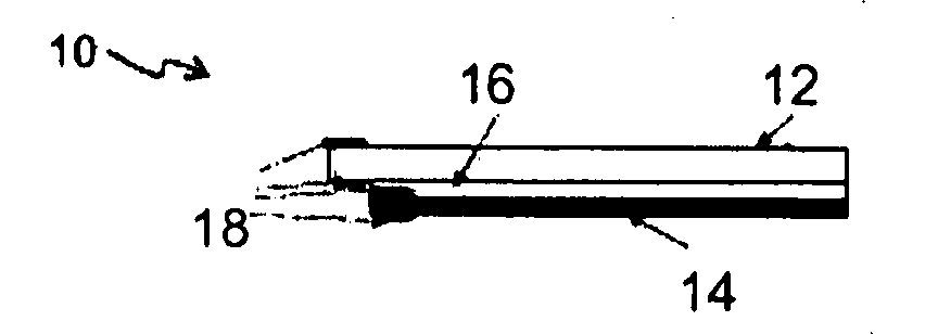
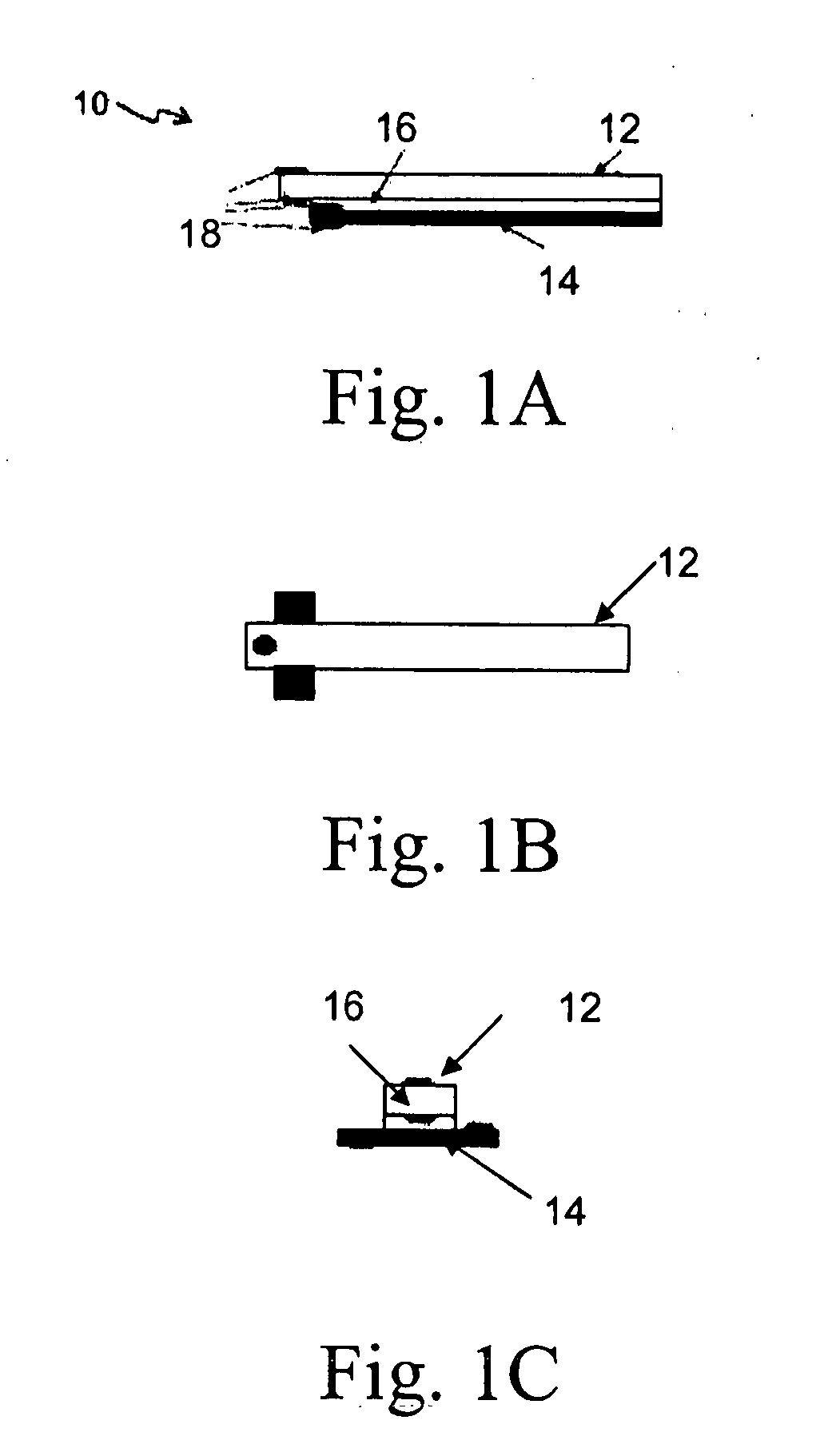
[0041]FIGS. 1A-1C illustrates an exemplary actuator 10. The actuator 10 is comprised generally of: an actuating member 12 made of an electroactive polymer; a sensing member 14 made of a piezoelectric material; and an insulating member 16 interposed between the actuating member 12 and the sensing member 14.

[0042]In the exemplary embodiment, the electroactive polymer is further defined as an ionic polymer-metal composite (IPMC). Different IPMC materials, having different dimensions, can be used. Such materials are commercially available from Environmental Robots Inc. Other types of electroactive polymers are contemplated by the broader aspects of this disclosure.

[0043]Likewise, different piezoelectric materials and different insulating materials can be used. In the exemplary embodiment, the sensing member is a polyvinylidene fluoride material; whereas, the insulating member is a polyvinyl chloride or polyester film. Other types of materials are also contemplated by this disclosure.

[00...


PUM


Abstract

An integrated sensory actuator (10) which uses an electroactive polymer is provided. The sensory actuator is comprised of an actuating member (12) made of an ionic polymer-metal composite; a sensing member (14) made of a piezoelectric material; and an insulating member (16) interposed between the actuating member and the sensing member. The sensory actuator may further include a compensation circuit adapted to receive a sensed signal from the sensing member and an actuation signal from the actuating member and compensate the sensed signal for feedthrough coupling between the actuating member and the sensing member.

Description

GOVERNMENT RIGHTS[0001]The U.S. Government may have a paid-up license in this invention, and may have the right, in limited circumstances, to require the patent owner to license others on reasonable terms as identified by the terms of Federal Grant Nos. CMS 0550651 and ECS 0547131 awarded by the National Science Foundation.FIELD[0002]The present disclosure relates generally to an integrated actuator-sensor structure which uses an electroactive polymer for actuation and a piezoelectric polymer for sensing.BACKGROUND[0003]Ionic polymer-metal composites (IPMCs) form an important category of electroactive polymers which has both built-in actuation and sensing capabilities. Due to their large bending displacement, low driving voltage, resilience, and biocompatibility, IPMCs have been explored for potential applications in biomimetic robotics, medial devices, and micromanipulators. In most of these applications, compact sensing schemes are desired for feedback control of IPMC actuators to...

Claims


Application Information

Patent Timeline
IPC IPC(8): G05B1/06H01L41/04
CPCH01L41/042Y10S310/80H01L41/0825H10N30/802H10N30/1071
Inventor TAN, XIAOBOXI, NINGCHEN, ZHENGSHEN, YAMTOA
Owner BOARD OF TRUSTEES OPERATING MICHIGAN STATE UNIV
Why Eureka
Try Eureka