
Optical voltage transformer

a voltage transformer and optical technology, applied in the field of optical voltage sensors, can solve the problems of limited downsizing, large main circuit section for generating main circuit voltage, and limited downsizing, and achieve the effect of accurate measurement and downsizing by reducing the number of its components

Inactive Publication Date: 2010-05-06
TOSHIBA ENERGY SYST & SOLUTIONS CORP +1
View PDF2 Cites 4 Cited by
  • Summary
  • Abstract
  • Description
  • Claims
  • Application Information

AI Technical Summary

Benefits of technology

[0011]This goes against recent trends of downsizing. Therefore, desired has been an optical voltage transformer that can achieve shorter insulating distance than that with insulation gas or ceramic capacitors and can reduce its cost and the number of its components.
[0012]It is an object of the present invention to provide an optical voltage transformer that can prevent its measurement accuracy from being affected by its surrounding environment such as temperature alteration and can achieve its downsizing by reducing the number of its components.
[0014]According to the above aspect, the optical voltage transformer can achieve accurate measurement without affected by its surrounding environment such as temperature alteration and can achieve its downsizing by reducing the number of its components.

Problems solved by technology

However, the above-mentioned optical transformer using insulation gas in the main circuit section needs to ensure a certain insulation distance according to dielectric strength of the insulation gas and thus its downsizing is limited.
In addition, the optical transformer using the ceramic capacitors needs the certain number of tandem alignments according to dielectric strength of the capacitors and thus its downsizing is limited.
Namely, in these optical voltage transformers, the main circuit section for generating main circuit voltage may become large.
Therefore, excessive works for its adjustment must be needed.

Method used


Image

  • Optical voltage transformer
  • Optical voltage transformer
  • Optical voltage transformer

Examples


Embodiment Construction

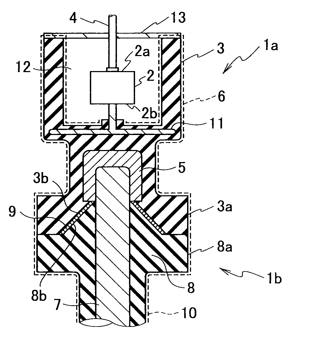
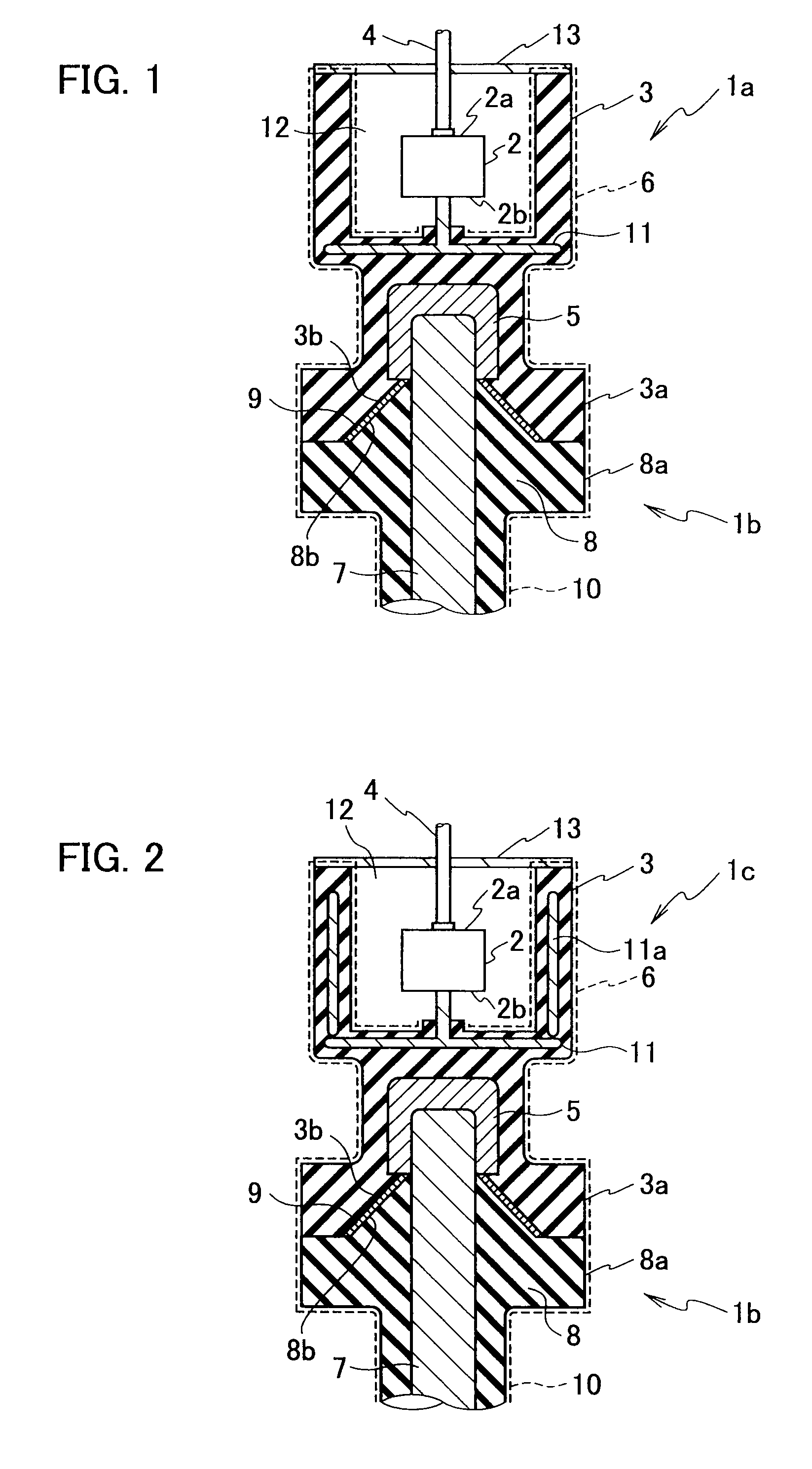
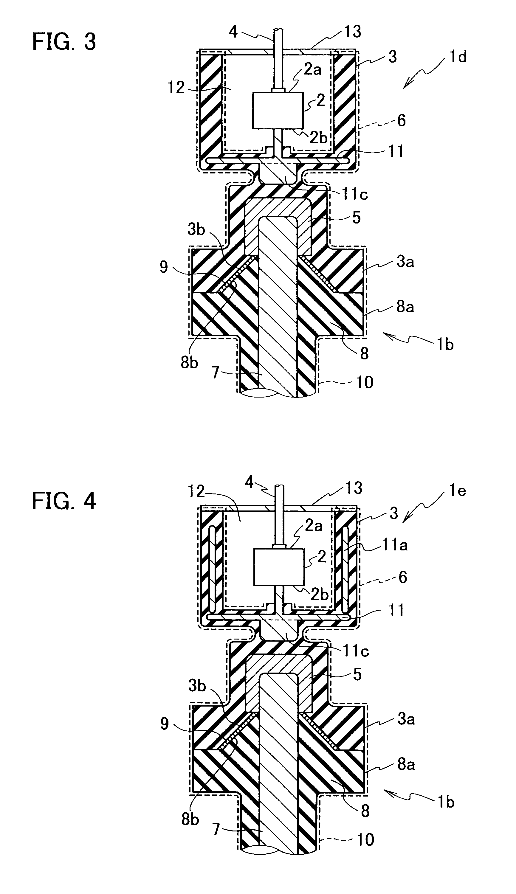
[0019]An optical voltage transformer according to a first embodiment of the present invention will be explained with reference to the drawings. As shown in FIG. 1, the optical voltage transformer is a voltage detector 1a composed of a primary electrode 5, a secondary electrode 11, an insulation layer 3, a ground layer 6, an electro-optic element 2, and a soft insulator 9. The optical voltage transformer is connected with an external electric device (e.g., a switchgear) via a main circuit device 1b.

[0020]The primary electrode 5 is connected with the external electric device and measured voltage is applied thereto by the external electric device. The primary electrode 5 is a cup-shaped electrode and electrically connected with a center conductor 7 of the main circuit device 1b.

[0021]The secondary electrode (first secondary electrode) 11 is opposed to the primary electrode 5 with interposing the insulation layer 3 to keep a predefined insulating distance.

[0022]The insulation layer 3 ...


PUM


Abstract

An optical voltage transformer is connected with an external electric device and includes a primary electrode to which a measured voltage is applied by the external electric device, a first secondary electrode provided oppositely to the primary electrode, an insulation layer provided between the primary and first secondary electrodes and constituting an insulation cylinder integrally formed with the primary and first secondary electrodes, a ground layer provided on an outer circumference of the insulation cylinder and around the first secondary electrode for securing a capacitance by interposing the insulation layer between the ground layer and the first secondary electrode, and an electro-optic element for measuring a voltage between the first secondary electrode and the ground layer. According to the optical voltage transformer, measurement of the measured voltage can be done with high accuracy without affected by its surrounding environment and its downsizing can be achieved by reducing the number of its components.

Description

TECHNICAL FIELD[0001]The present invention relates to an optical voltage sensor for measuring main circuit voltage in an electric device, such as a switchgear, using an electro-optic effect (Pockels effect), i.e., an optical voltage transformer.BACKGROUND ART[0002]In an electric device such as a switchgear, a wire-wound type voltage transformer is used for protecting a main circuit or measuring in the main circuit. Recently, an optical voltage transformer that provides advantages, such as anti-inductance, broad spectrum and electric insulation, is widely used.[0003]As this sort of an optical voltage transformer, known is an optical voltage transformer that includes a main circuit section filled with insulation gas, a voltage dividing capacitor connected with the main circuit section, and an optical sensor with electro-optic element. An optical potential transducer disclosed in a Patent Document 1 shown below is an equivalent device to an optical voltage transformer. The optical pote...

Claims


Application Information

Patent Timeline
IPC IPC(8): G01R13/38
CPCG01R15/241G01R15/06G01R15/247G01R15/242G01R15/16G01R15/24G01R19/00
Inventor SATO, JUNICHITAKAHASHI, MASAOTAKEUCHI, MIWAMAEDA, TERUHIKOFUJIKAWA, MITSUHIROUMEMURA, TOKIHIROKUWABARA, TSUYOSHI
Owner TOSHIBA ENERGY SYST & SOLUTIONS CORP
Learn More