Current sensing inductor and a circuit thereof

a current sensing inductor and circuit technology, applied in the direction of transformers/inductance coils/windings/connections, base element modifications, etc., can solve the problems of large power loss, significant power loss of 1 w, and the current sensing circuit in fig. 2 is not suitable for continuous-inductor-current-mode operation, etc., to achieve accurate inductor current detection and eliminate power loss

Inactive Publication Date: 2010-05-06
PI INT
View PDF5 Cites 16 Cited by
  • Summary
  • Abstract
  • Description
  • Claims
  • Application Information

AI Technical Summary

Benefits of technology

[0010]The object of the invention is to provide a means for accurate inductor current detection without the need of a current sensing resistor, a current sensing transformer, or a strong low-pass filtering circuit, thereby eliminating the power loss associated with a current sensing resistor, the inaccuracy with a current sensing transformer, and the response delay due to a strong low-pass filtering circuit.
[0012]Another aspect of the present invention is to provide a current sensing inductor, and a circuit thereof that eliminate inaccuracy due to thermal drift in the resistive voltage drop. The current sensing inductor has a detection winding which is connected in series with the existing winding of the inductor to form a serial circuit. The detection winding of the inductor is composed of an inductive portion and a non-inductive (fieldless) portion. The inductive portion is magnetically coupled with the existing winding. The induction voltage of the inductive portion in the detection winding is used to cancel the induction voltage of the existing winding. Because of this cancellation, the voltage across the serial circuit becomes a resistive voltage drop of the current flowing through the existing winding. The non-inductive portion has a DC resistance which is significantly higher than, and in a fix proportion with, that of the existing winding. This fix proportion is insensitive to ambient temperature change as both the existing and the detection windings are built with the same material and subjected to the same temperature. When a reference current flows through the detective winding, a reference voltage is developed across the non-inductive portion of the detection winding. The reference voltage is used to cancel the voltage drop generated by an inductor current flowing through the existing winding. Therefore, when the voltage across the serial circuit is zero, the inductor current and the reference current is known to be in the aforementioned fix proportion.

Problems solved by technology

Although the voltage drop across the current sensing resistor 12 is low, the power loss can be large when the inductor current is high.
For example, when the voltage drop is 50 mV but the inductor current is 20 A, a significant power loss of 1 W is resulted.
However, the current sensing circuit in FIG. 2 is not suitable for continuous-inductor-current-mode operation.
Even though, the accuracy of this sensing circuit is suffered from magnetising current within the current sensing transformer 22 when the inductor current flows uninterrupted for too long a period.
But the strong low-pass filter introduces heavy delay to the detection response time.
That makes control loop compensation difficult.
That makes current sensing very inaccurate.

Method used


Image

  • Current sensing inductor and a circuit thereof
  • Current sensing inductor and a circuit thereof
  • Current sensing inductor and a circuit thereof

Examples


Embodiment Construction

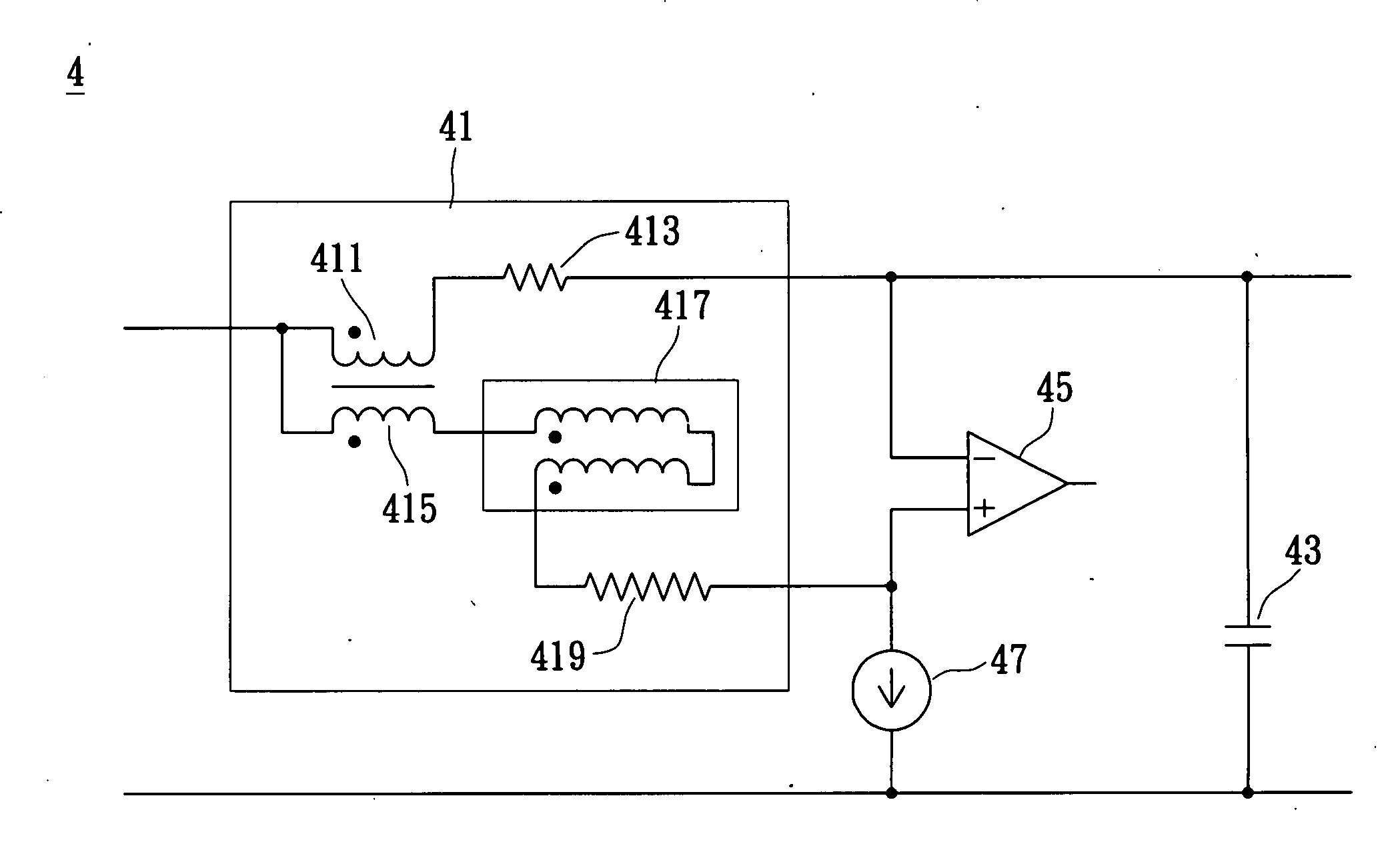
[0021]The present invention provides a current sensing inductor and a current sensing circuit. A detection winding is added to the inductor and the induction voltage of the detection winding is used for canceling the induction voltage of the existing inductor winding to provide a pure resistive voltage drop for current sensing. It requires no sensing resistors or low-pass filters. Therefore, problems in prior arts, such as power loss or response time delay, are mitigated.

[0022]Key features of the present invention are the design of the inductor and the application of the inductor in the current sensing circuit. These features are described below.

[0023]Reference is made to FIG. 4, which shows a circuit diagram of the current sensing circuit of the first and preferred embodiment of the present invention. This figure exemplifies the output section of a buck or forward converter. The current sensing circuit 4 includes an inductor 41 and a sensing amplifier 45. The inductor 41 includes a...


PUM

PropertyMeasurementUnit
power lossaaaaaaaaaa
induction voltagesaaaaaaaaaa
currentaaaaaaaaaa

Abstract

An inductor design having a detection winding which is magnetically coupled to the existing winding and its induction voltage is used to cancel that of the existing winding. Having the induction voltage cancelled, the voltage across the existing winding represents a resistive voltage drop of the existing winding current. The detection winding is furthermore built with a non-inductive portion having a significantly higher DC resistance in proportion to that of the existing winding. This resistance proportion is insensitive against temperature variations when both the existing and the detection windings are built with the same material and subjected to the same environment. A reference current is fed through the detection winding to produce a reference resistive voltage drop which is used to cancel the resistive voltage drop across the existing winding. When a precise cancellation occurs, the existing winding current is known to be in exact proportion to the reference current.

Description

BACKGROUND OF THE INVENTION[0001]1. Field of the Invention[0002]The present invention relates to the constructions of an inductor and a circuit thereof. In particular, the present invention relates to a current sensing inductor and a circuit thereof.[0003]2. Description of Related Art[0004]Inductors are commonly used in switched mode power conversion circuits for energy storage and for current and voltage filtering. In those applications, the instantaneous current flowing through inductor is a critical parameter for proper control circuit operation. Therefore, a variety of methods for measuring inductor current have been proposed.[0005]Reference is made to FIG. 1, which shows a circuit diagram of a current sensing circuit of the prior art, wherein the circuit shows the output portion of the buck or forward type converter. As shown in FIG. 1, the current sensing circuit 1 includes an inductor 11, a current sensing resistor 12, and a sensing amplifier 15. The inductor 11 includes an i...

Claims


Application Information

Patent Timeline
Patent Type & Authority Applications(United States)
IPC IPC(8): G01R1/20H01F27/28
CPCG01R1/203G01R15/181H01F17/00H01F27/38H01F38/32
Inventor CHEUNG, CHI HUNG
Owner PI INT
Why Eureka
Try Eureka