Surface mount pulse transformer and method and apparatus for manufacturing the same

a pulse transformer and surface mount technology, applied in the direction of magnets, inductances, magnetic bodies, etc., can solve the problems of increasing manufacturing costs, and achieve the effect of reducing winding job tim

Active Publication Date: 2010-05-06
TDK CORPARATION
View PDF0 Cites 140 Cited by
  • Summary
  • Abstract
  • Description
  • Claims
  • Application Information

AI Technical Summary

Benefits of technology

[0013]Accordingly, an object of the invention is to provide a surface mount pulse transformer capable of reducing a winding job time when a winding job is performed using an automatic winder which performs the winding job only to one of flanges at a time and a manufacturing method and a manufacturing apparatus of the same.
[0024]As described above, according to the invention, a winding job time can be reduced when a winding job of a surface mount pulse transformer is performed using an automatic winder capable of performing a wire connection job of only one of flanges at a time.

Problems solved by technology

However, in the conventional surface mount pulse transformer, since the wires are alternately connected to the flanges 2b, 2c as shown in FIGS. 18A to 18H, the conventional surface mount pulse transformer has a problem in that when a winding job is performed using an automatic winder which performs a winding job only to one of the flanges at a time, a long time is required for the winding job, which causes increase of manufacturing cost.

Method used


Image

  • Surface mount pulse transformer and method and apparatus for manufacturing the same
  • Surface mount pulse transformer and method and apparatus for manufacturing the same
  • Surface mount pulse transformer and method and apparatus for manufacturing the same

Examples


Embodiment Construction

[0043]A preferred embodiment of the invention will be described below in detail with reference to the accompanying drawings.

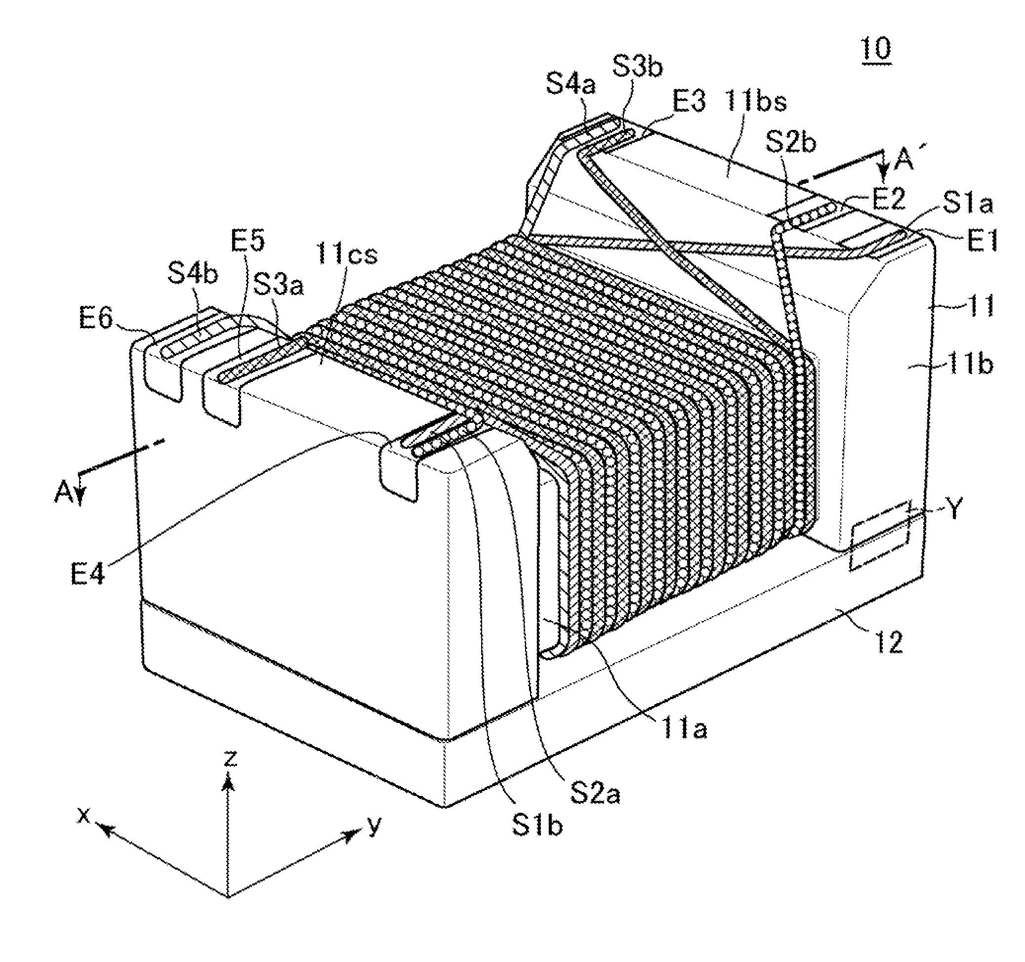
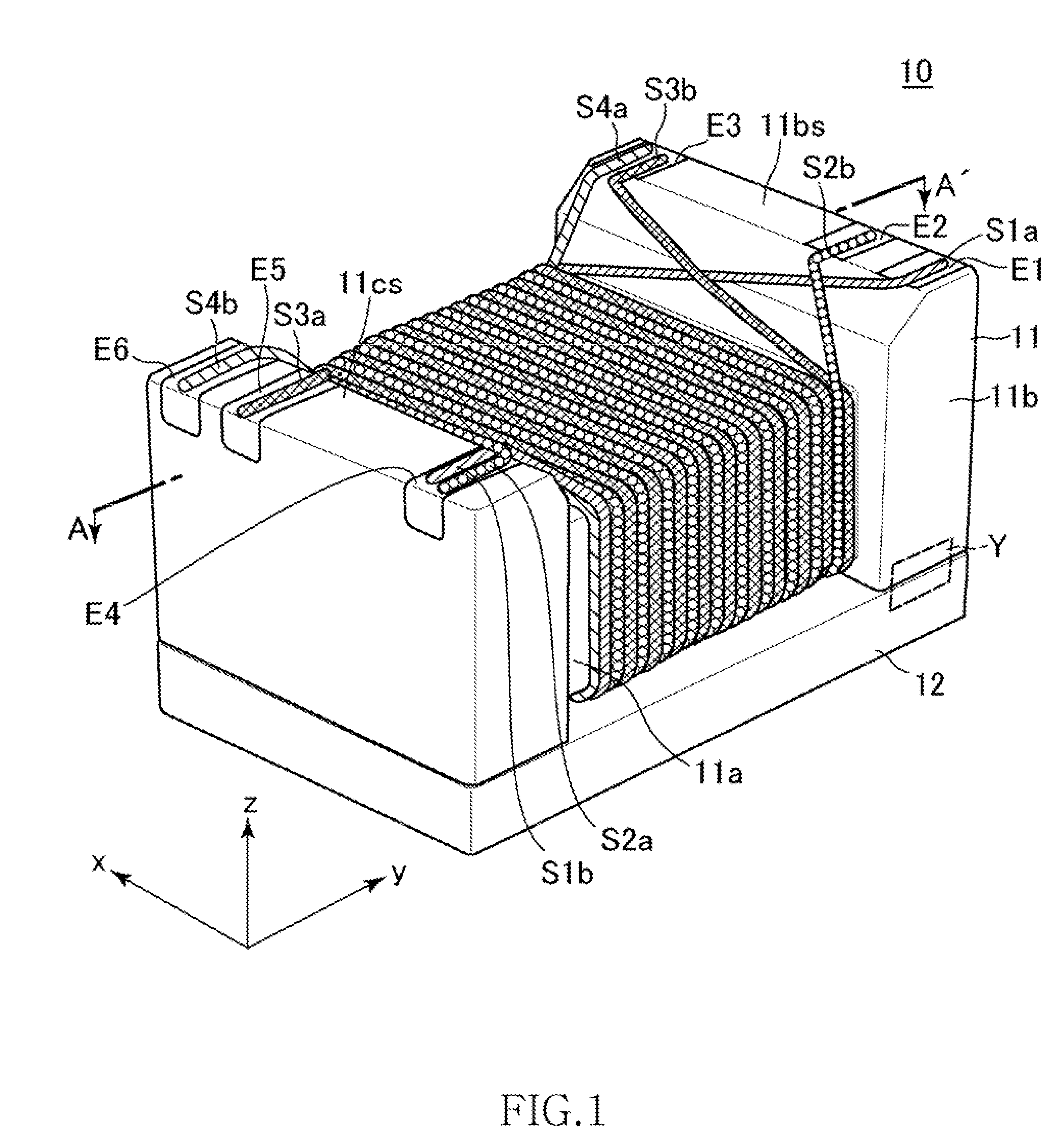
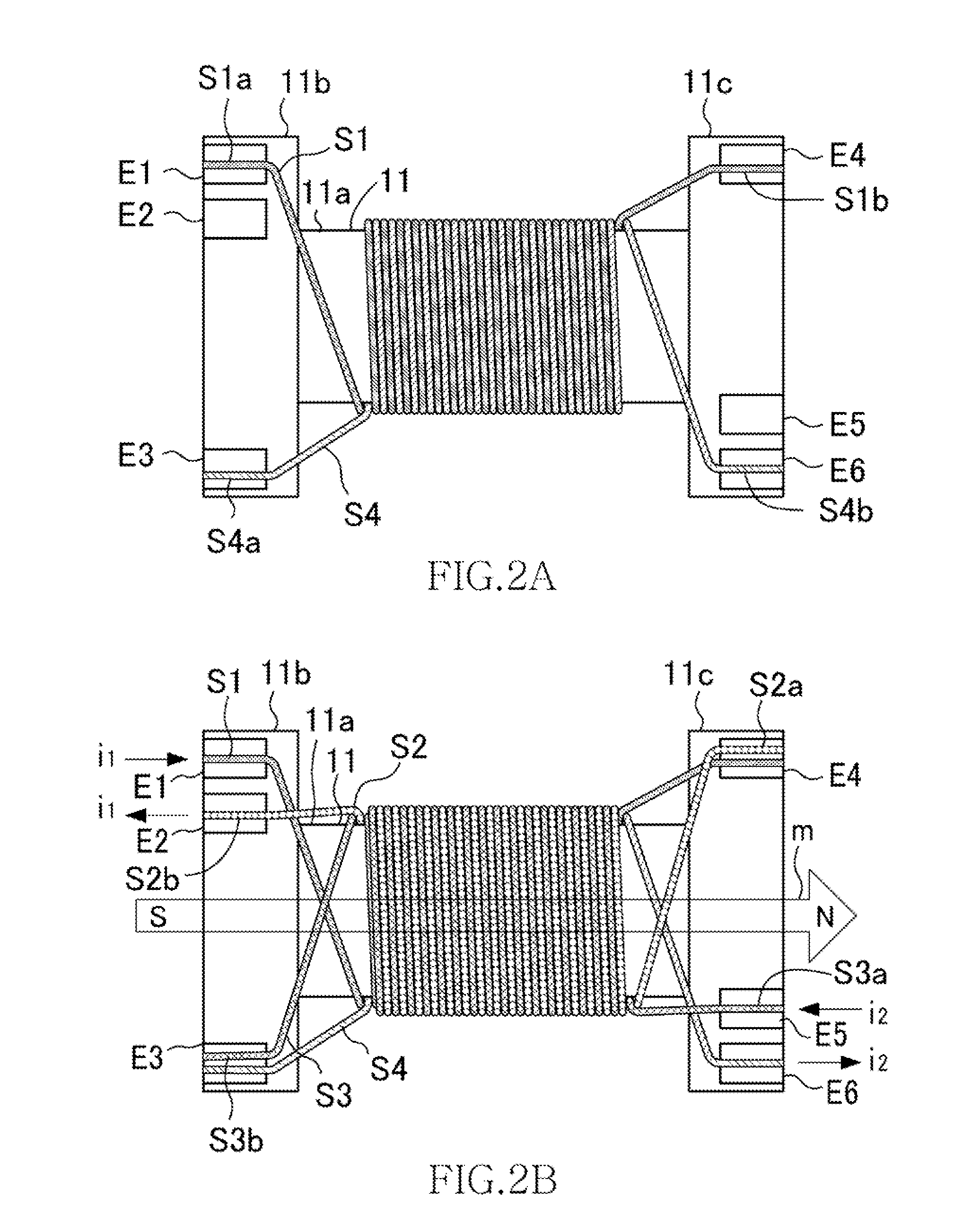
[0044]FIG. 1 is a schematic perspective view showing an external appearance structure of a surface mount pulse transformer 10 according to a preferred embodiment of the invention. FIGS. 2A and 2B are plan views of the surface mount pulse transformer 10. FIG. 2A shows only wires of a first layer, and FIG. 2B shows also wires of a second layer. FIG. 3 is a sectional view taken along the line A-A′ of FIG. 1 and shows a winding structure of the respective wires in detail. An arrangement of the surface mount pulse transformer 10 will be described below with reference to the drawings.

[0045]As shown in FIGS. 1, 2A and 2B, the surface mount pulse transformer 10 has a drum core 11, a sheet-shaped core 12 attached to the drum core 11, and wires S1 to S4 wound around the drum core 11.

[0046]The drum core 11 has a rod-shaped core 11a and flanges 11b, 11c disposed to both en...


PUM

PropertyMeasurementUnit
separation distancesaaaaaaaaaa
separation distanceaaaaaaaaaa
voltageaaaaaaaaaa

Abstract

A surface mount pulse transformer has a drum type core including a core and first and second flanges disposed on both ends of the core and installed on a substrate and a primary winding wire and a secondary winding wire wound around the core and provided with an intermediate tap, respectively, wherein first and second terminal electrodes being connected to each of both ends of the primary winding wire and a third terminal electrode for connecting being connected to the intermediate tap of the secondary winding wire are disposed on the surface of the first flange and a fourth terminal electrode being connected to the intermediate tap of the primary winding wire and fifth and sixth terminal electrodes being connected to each of both ends of the secondary winding wire are disposed on the surface of the second flange.

Description

TECHNICAL FIELD[0001]The invention relates to a surface mount pulse transformer and a method and an apparatus for manufacturing the same.BACKGROUND OF THE INVENTION[0002]When equipment such as a personal computer and the like are connected to networks such as a LAN, a phone network, and the like, it is necessary to protect the equipment from an ESD (Electrostatic Discharge) and a high voltage which intrude therein through a cable. To cope with the above problem, a pulse transformer is used for a connector constituting a connection point of the cable and the equipment.[0003]A conventionally used pulse transformer is composed of a doughnut-shaped core (toroidal core) and a primary coil and a secondary coil wound around the core (refer to, for example, Japanese Patent Application Laid-Open No. 7-161535) and has a property for transmitting only the alternating component (pulses) of a voltage applied to the primary coil to the secondary coil. Since a direct current component is not trans...

Claims


Application Information

Patent Timeline
Patent Type & Authority Applications(United States)
IPC IPC(8): H01F27/29H01F41/10
CPCH01F17/045H01F27/292H01F2019/085Y10T29/49071H01F41/069H01F41/076
Inventor ASOU, HIROHUMIYASUDA, MITSUTAKASARIISHI, SATORUKITAHARA, SATORU
Owner TDK CORPARATION
Why Eureka
Try Eureka