
Measurement apparatus

a technology of measurement apparatus and measuring distance, which is applied in the direction of measurement devices, instruments, interferometers, etc., can solve the problems of difficult to improve the measurement accuracy of geometric distance d, the need to increase the wavelength difference, and the difficulty of ensuring the precision of a polarizer, etc., to achieve the effect of high accuracy

Inactive Publication Date: 2010-05-06
CANON KK
View PDF1 Cites 15 Cited by
  • Summary
  • Abstract
  • Description
  • Claims
  • Application Information

AI Technical Summary

Benefits of technology

The present invention provides a measurement apparatus that can accurately measure the distance between two surfaces. The apparatus uses an optical frequency comb to generate a light beam with multiple optical frequency components, which are detected by a detection unit. The detection unit detects an interference signal between the reflected light beams, and the calculation unit calculates the geometric distance between the surfaces based on the detected phase. The apparatus can provide high accuracy in measuring the optical path between surfaces.

Problems solved by technology

Unfortunately, the prior art poses a problem in that the measurement accuracy of the geometric distance D is difficult to improve because the measurement accuracy depends on the coefficient A. For example, although a reduction in coefficient A can improve the measurement accuracy, it makes it necessary to increase the wavelength difference.
This, in turn, makes it difficult to guarantee the precision of a polarizer, resulting in periodic errors of the optical path length.
Another problem is that the coefficient A is more than 10 or 20 even at a minimum in a typical wavelength range and is therefore inevitably prone to be large when compared to the measurement accuracy of the optical path length.
Still another problem is that the difference in optical path length measured actually has an uncertainty of an integer multiple of the wavelength.
This means that absolute value determination is practically impossible.

Method used


Image

  • Measurement apparatus
  • Measurement apparatus
  • Measurement apparatus

Examples


first embodiment

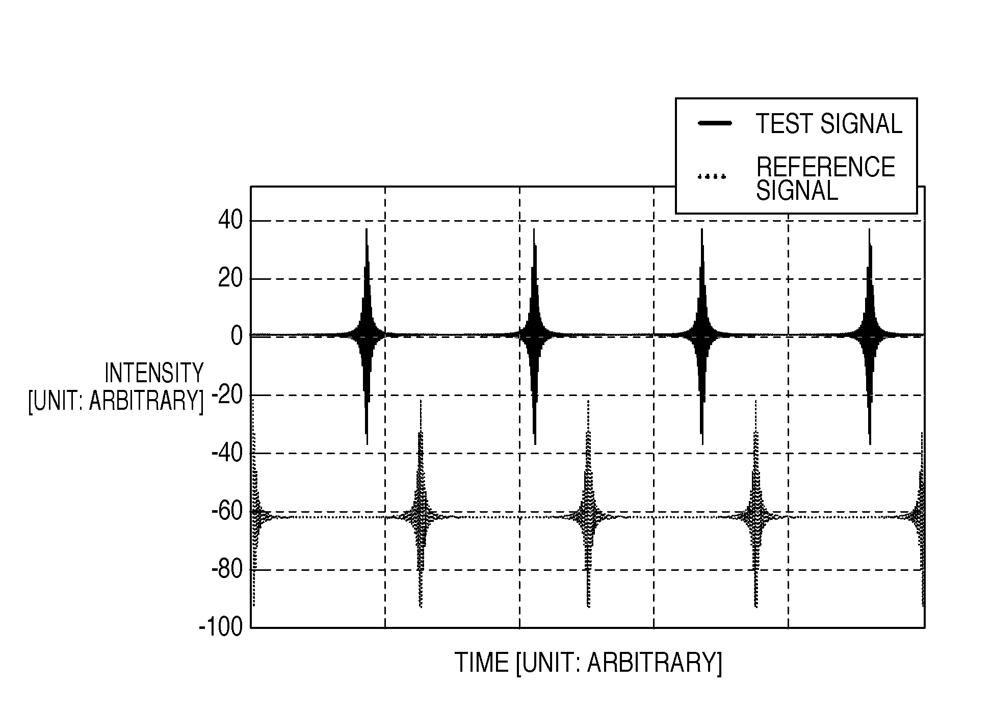
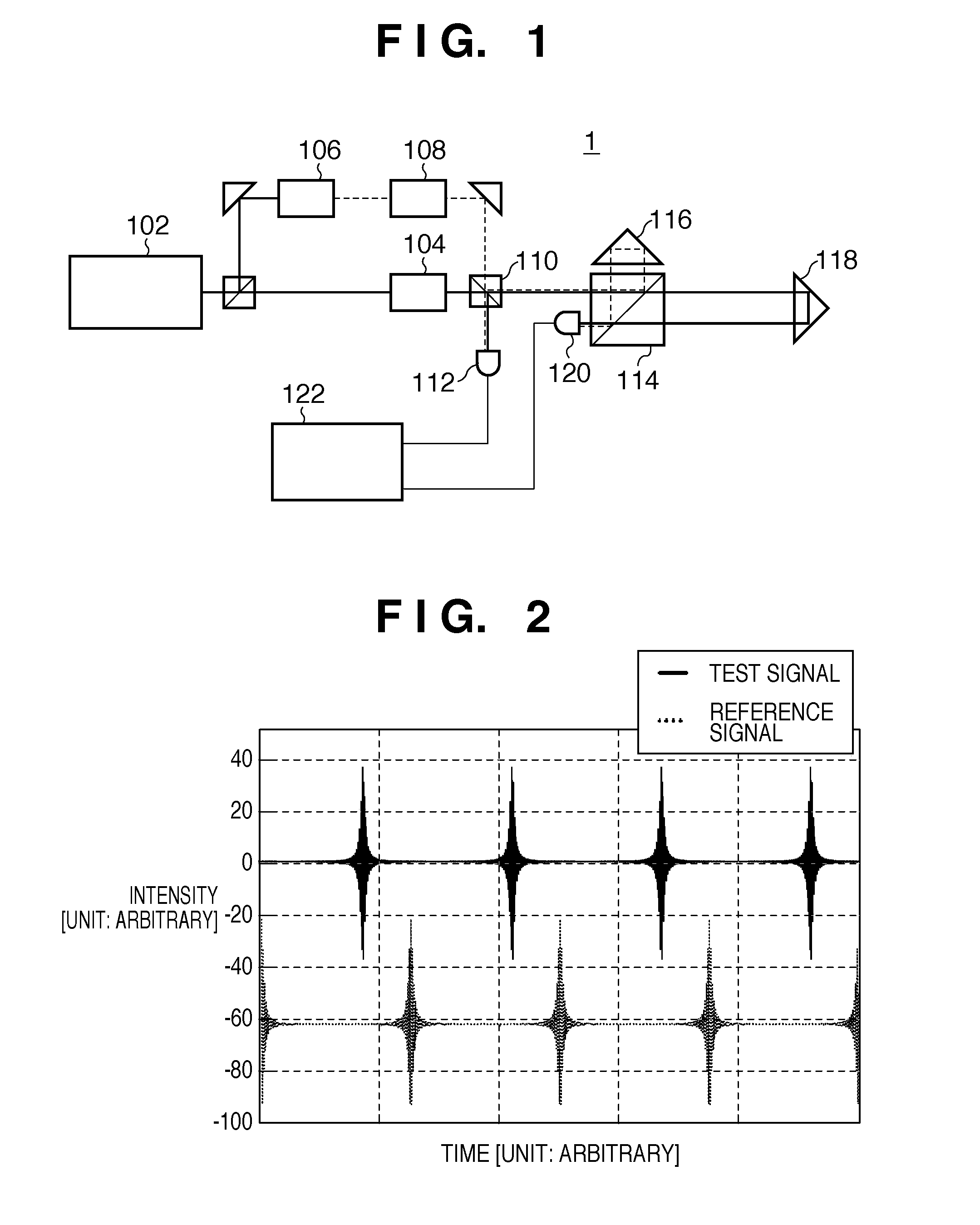
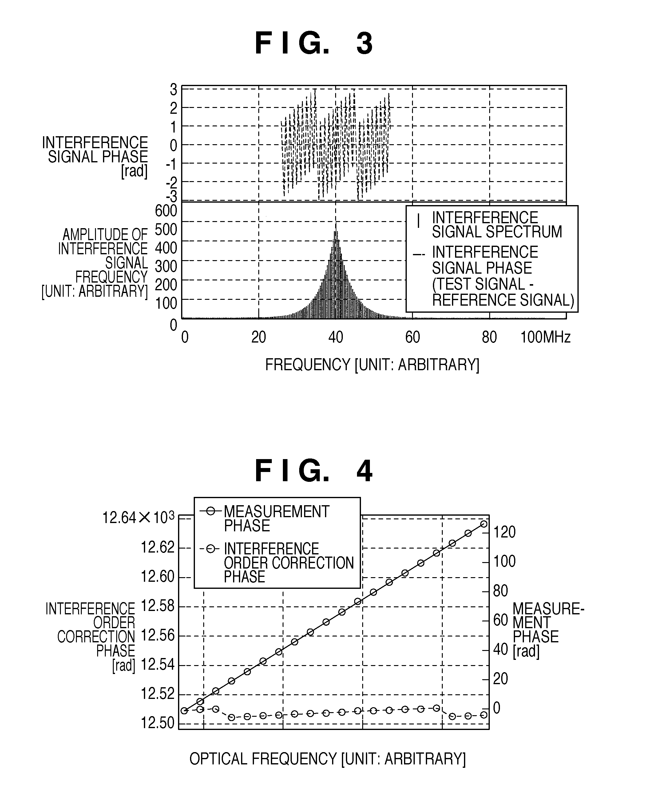
[0034]FIG. 1 is a block diagram showing the arrangement of a measurement apparatus 1 according to the first embodiment. The measurement apparatus 1 is a light wave interferometric measurement apparatus which measures the distance between a reference surface fixed on a fiducial surface and a test surface located on a test object. As shown in FIG. 1, the measurement apparatus 1 includes a light source 102, optical frequency comb generation unit (first unit) 104, frequency shifter 106, and optical frequency comb generation unit (second unit) 108. The measurement apparatus 1 also includes a non-polarizing beam splitter 110, reference signal detection unit 112, polarizing beam splitter 114, test signal detection unit 120, and calculation unit 122. Although the measurement apparatus 1 includes one set of optical frequency comb generation units, it may include more than one set.

[0035]A light beam (specifically, a light beam having a wavelength stabilized with high accuracy), which has an o...

second embodiment

[0064]FIG. 6 is a block diagram showing the arrangement of a measurement apparatus 1A according to the second embodiment. The measurement apparatus 1A is a light wave interferometric measurement apparatus which measures the distance between a reference surface fixed on a fiducial surface and a test surface located on a test object. The measurement apparatus 1A includes a plurality of sets of optical frequency comb generation units. One set includes two units which generate light beams having different center optical frequencies and optical frequency separations.

[0065]As shown in FIG. 6, the measurement apparatus 1A includes a light source 102, optical frequency comb generation unit 104, frequency shifter 106, and optical frequency comb generation unit 108. The measurement apparatus 1A also includes a non-polarizing beam splitter 110, reference signal detection unit 112, polarizing beam splitter 114, test signal detection unit 120, and calculation unit 122. The measurement apparatus ...


PUM


Abstract

The present invention provides a measurement apparatus which measures a distance between a reference surface fixed on a fiducial surface and a test surface located on a test object, the apparatus including an optical frequency comb generation unit configured to generate a light beam with a plurality of optical frequency components, which have equal optical frequency separations therebetween, a detection unit configured to, for at least two of the plurality of optical frequency components, detect an interference signal between a light beam reflected by the reference surface and a light beam reflected by the test surface to detect a phase corresponding to an optical path length between the reference surface and the test surface, and a calculation unit configured to calculate a geometric distance between the reference surface and the test surface based on the phases detected by the detection unit.

Description

BACKGROUND OF THE INVENTION[0001]1. Field of the Invention[0002]The present invention relates to a measurement apparatus.[0003]2. Description of the Related Art[0004]A light wave interferometric measurement apparatus (to be simply referred to as a “measurement apparatus” hereinafter) has been conventionally employed to measure the geometric distance of the optical path between a reference surface and a test surface (that distance assuming that the reference surface and the test surface have a vacuum space between them).[0005]A measurement apparatus 1000 having a correction function for a fluctuation in refractive index will be explained with reference to FIG. 10. A light beam (specifically, a light beam having a wavelength stabilized with high accuracy) from a light source 1010 enters a wavelength conversion unit 1020. The wavelength conversion unit 1020 generates not only the optical frequency component (i.e. a fundamental harmonic component) of the incident light beam but also an ...

Claims


Application Information

Patent Timeline
Patent Type & Authority Applications(United States)
IPC IPC(8): G01B11/02
CPCG01B11/14G01B9/02007G01B9/02003G01B9/0207G01B9/02008G01B2290/70
Inventor KURAMOTO, YOSHIYUKI
Owner CANON KK
Learn More