Network switch cooling system

a network switch and cooling system technology, applied in the direction of cooling/ventilation/heating modifications, electrical apparatus casings/cabinets/drawers, instruments, etc., can solve the problems of less effective heat transfer, electrical components contained within the chassis generate a significant amount of heat, and may cause thermal damage to electronic components

Active Publication Date: 2010-05-06
ARISTA NETWORKS
View PDF11 Cites 24 Cited by
  • Summary
  • Abstract
  • Description
  • Claims
  • Application Information

AI Technical Summary

Benefits of technology

[0012]The advantages of the present invention are three-fold. First, the present invention provides a single network switch chassis that can be mounted in the front of the rack with front-to-rear airflow, or in the rear-of-the-rack with rear-to-front airflow, where front refers to the side of the switch that has the networking ports. Advantageously, this avoids the need for custom switch desig

Problems solved by technology

The electronic components contained within the chassis generate a significant amount of heat.
Thermal damage may occur to the electronic components unless the heat is removed properly.
What is important for proper cooling is that cool air is available from the environment and that there is no re-circulation of heated air back into the chassis since this could result in less effective heat transfer and could cause the switch to overheat and potentially sustain thermal damage.
The conventional side-to-side or side-to-rear airflow design for network switches poses significant problems when deploying high performance networking switches in conjunction with rack-mounted servers or storage units that use front-to-back cooling, where air flows from the front of the chassis to the rear of the chassis.
Using side-to-side or side-to-rear airflow network switches in the same rack as front-to-rear airflow servers creates hot air recirculation and potential overheating for

Method used


Image

  • Network switch cooling system
  • Network switch cooling system
  • Network switch cooling system

Examples


Embodiment Construction

[0017]This invention relates to the design of high-performance network switches to provide appropriate cooling. Aspects of the invention assist with combining the networking switch with server and storage units in an industry standard rack and to allow for cooling redundancy and the hot-swapping of fans without interrupting the operation of the networking switch.

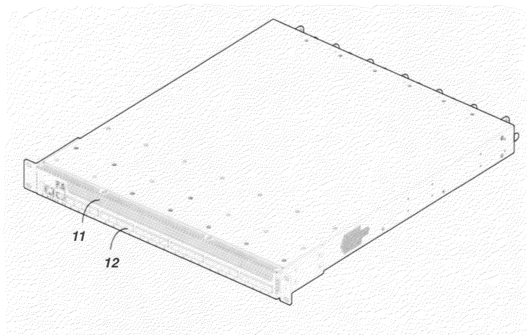
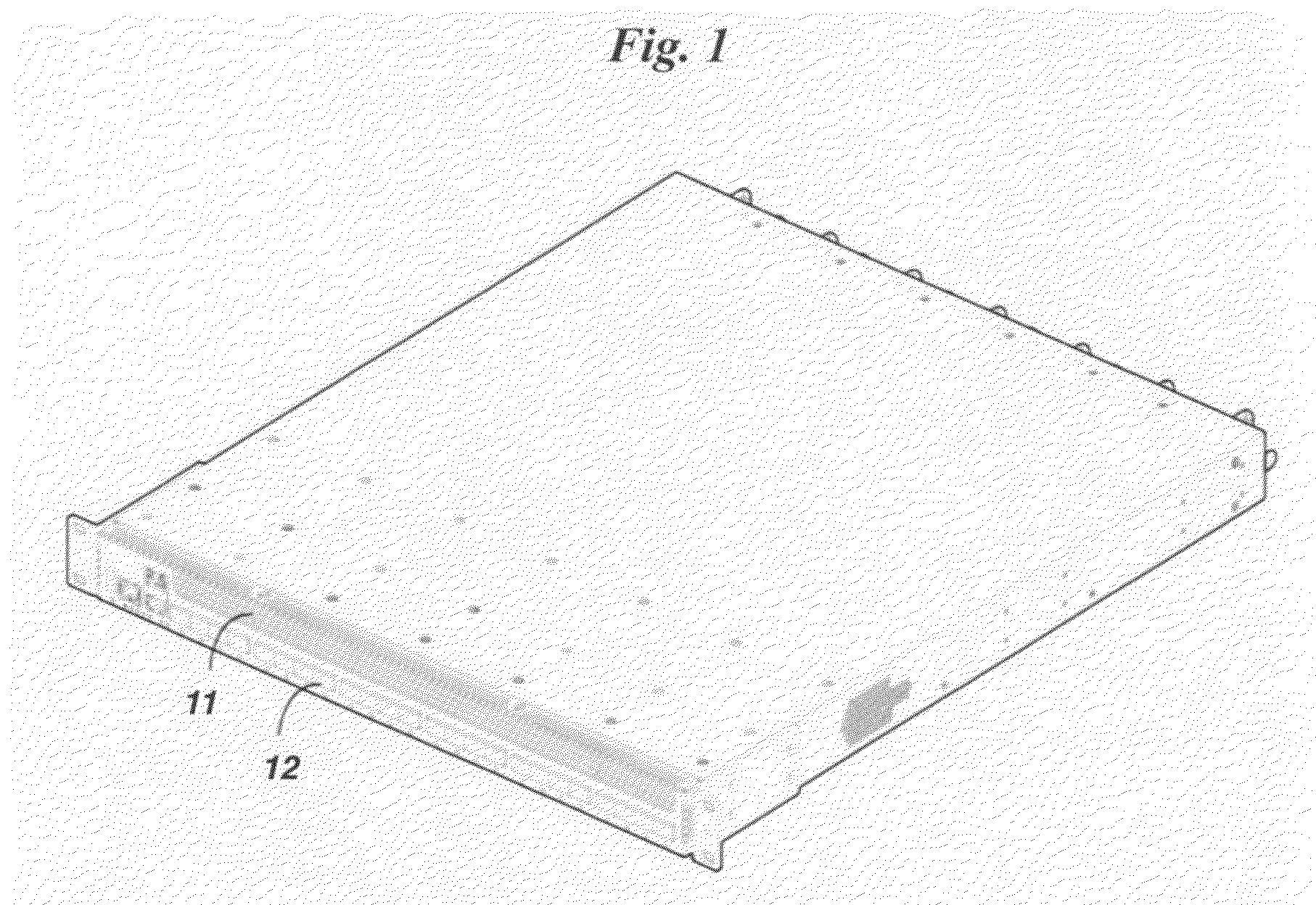
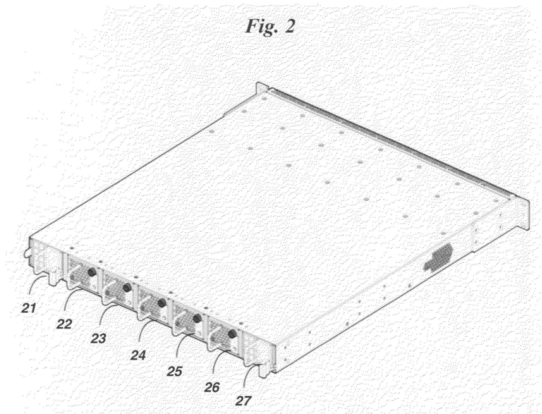
[0018]FIGS. 1 and 2 are perspective drawings of an example switch chassis according to an embodiment of the invention. FIG. 1 shows the front end of the chassis, FIG. 2 shows the rear end of the chassis. The switch chassis shown in FIGS. 1 and 2 is a IU rack mounted chassis that provides a 24-port 10 Gigabit Ethernet switch.

[0019]The example switch chassis is designed to fit into an industry-standard 19″ rack with dimensions that are approximately 1.75″ high, 17.5″ wide, and 20″ deep. The front of the chassis has air openings 11 located above the networking ports 12. Air openings 11 allow air to enter or exit the chassis. Th...


PUM


Abstract

A high-performance network switch chassis has multiple network ports and air openings on the front end of the chassis, and multiple fan modules mounted on the back end of the chassis. The fan modules are hot-swap replaceable so that replacement of one of the fan modules does not require interruption of network switch operation. Air-blockers associated with each fan module prevent recirculation of air when fan modules are removed. Different types of fan modules may be used to provide either front-to-rear or rear-to-front airflow through the chassis. A fan speed controller determines fan speed based on temperature using one of two profiles. The two profiles correspond to the two different airflow directions.

Description

FIELD OF THE INVENTION[0001]The present invention relates generally to network switch chassis designs. More specifically, it relates to cooling systems for a network switch chassis.BACKGROUND OF THE INVENTION[0002]Network switches are commonly enclosed within a chassis for support, physical security and efficient usage of space. The electronic components contained within the chassis generate a significant amount of heat. Thermal damage may occur to the electronic components unless the heat is removed properly.[0003]Proper removal of the heat requires fans that draw low temperature air into the switch chassis from one side and push out the heated air on another side of the chassis. What is important for proper cooling is that cool air is available from the environment and that there is no re-circulation of heated air back into the chassis since this could result in less effective heat transfer and could cause the switch to overheat and potentially sustain thermal damage.[0004]Network...

Claims


Application Information

Patent Timeline
IPC IPC(8): H05K7/20
CPCH05K7/20727
Inventor ROSE, ALEXANDER E.OYSGELT, ALEKSANDR
Owner ARISTA NETWORKS
Why Eureka
Try Eureka