Noise reduction device

Active Publication Date: 2010-05-06
PANASONIC INTELLECTUAL PROPERTY MANAGEMENT CO LTD
View PDF12 Cites 29 Cited by
  • Summary
  • Abstract
  • Description
  • Claims
  • Application Information

AI Technical Summary

Benefits of technology

[0013]Due to such a configuration, the cavity of the shell portion at the seat can be used as a cabinet for the control sound output unit (speaker), making it possible to increase the volume of the cabinet. As is obvious to the person in charge of the work, a speaker having a larger cabinet is higher in capacity of reproducing low-frequency sound and less in reproduction delay of low-frequency sound, and it is possible to enhance the noise reduction effect in low frequency ranges. Also, the holding strength of the control sound output unit can be enhanced. Further, comparing with such a case that the control sound output unit is built into the back of a chair in the seat, it brings about the following advantages. Firstly, the volume of the ca

Problems solved by technology

In airplanes and trains which generate considerable noise, when information is offered by voice service to the users, problems arise with noise generated at the seats.
In use of an inside space whose boundary is formed by a continuous wall as in an airplane or a train, the place used is a kind of closed structure, and if noise sources exist inside and outside the place used, it will cause a noise environment to be fixed for the users.
As a result, although it depends upon the level of noise, the noise exerts physical and mental pressure upon the user, worsening the comfortability of the place used.
Particularly, in the case of offering a service to the passengers in the cabin of an airplane, worsening of the comfortability will give serious hindrance to the quality of service operation.
In this case, inside noise makes the passengers feel uncomfortable and also causes hindrance to the voice service.
As the weight increases, it causes the flying fuel to increase, and the flying distance to shorten.
Accordingly, it results in worsening of the economy and function as an airplane.
Also, as a structural material, lowering of the strength such as being easy to be damaged and worsening of the design function such as quality of the touch c

Method used


Image

  • Noise reduction device
  • Noise reduction device
  • Noise reduction device

Examples


embodiment

Preferred Embodiment

[0060]Regarding the noise reduction device in the preferred embodiment of the present invention, an example of installing the device in an airplane is described in the following.

[0061]First, sound environment in an airplane required to be provided with a noise reduction device is described with reference to FIG. 1 and FIG. 2.

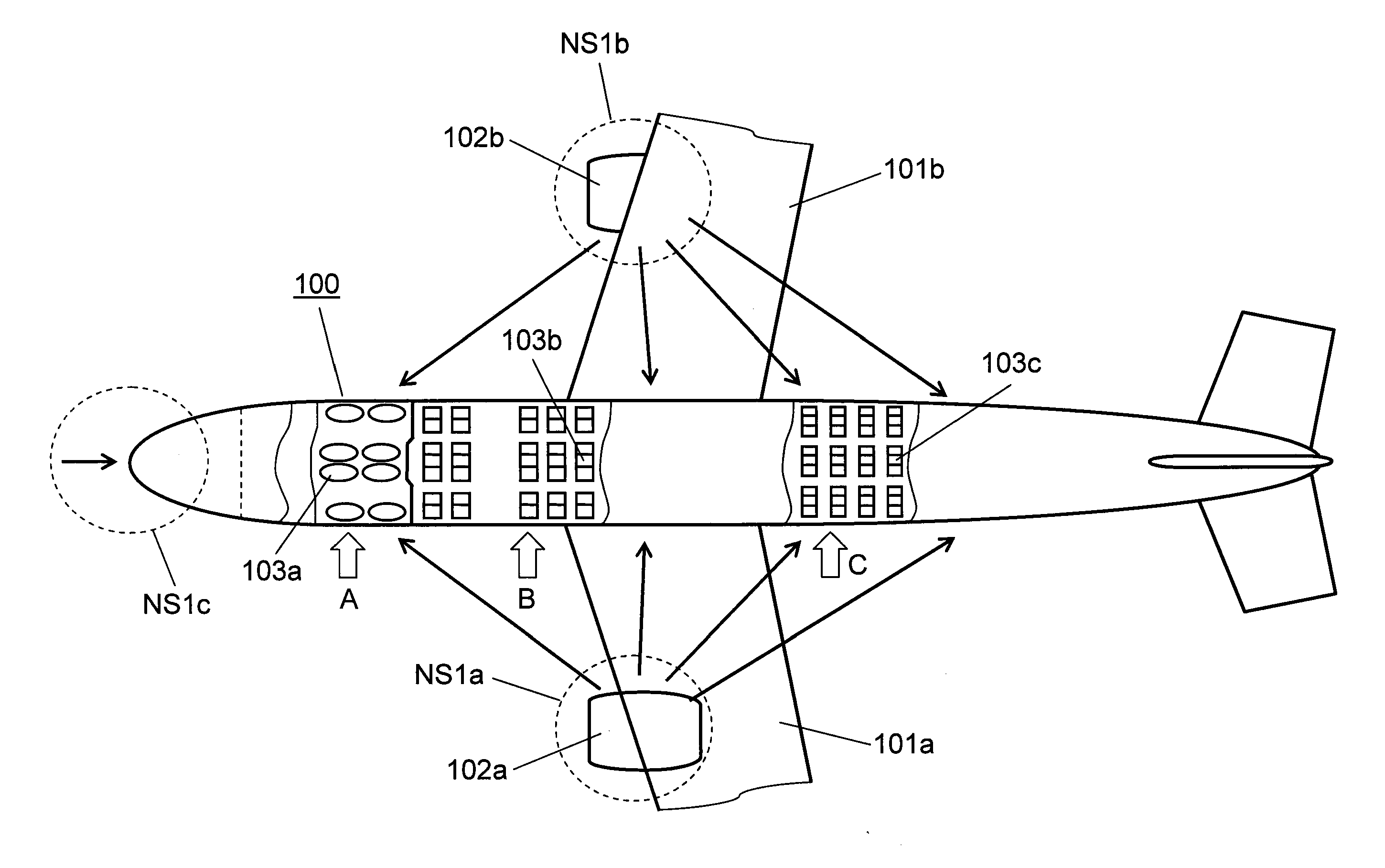
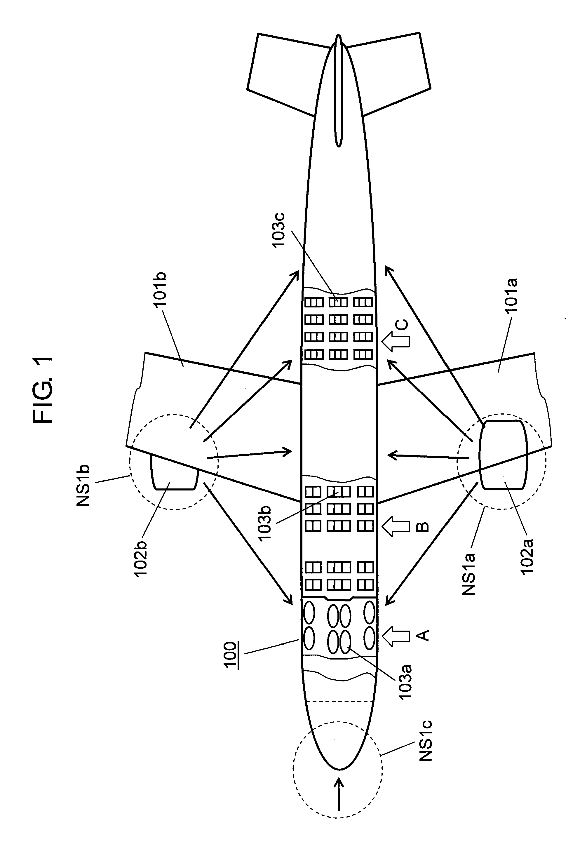
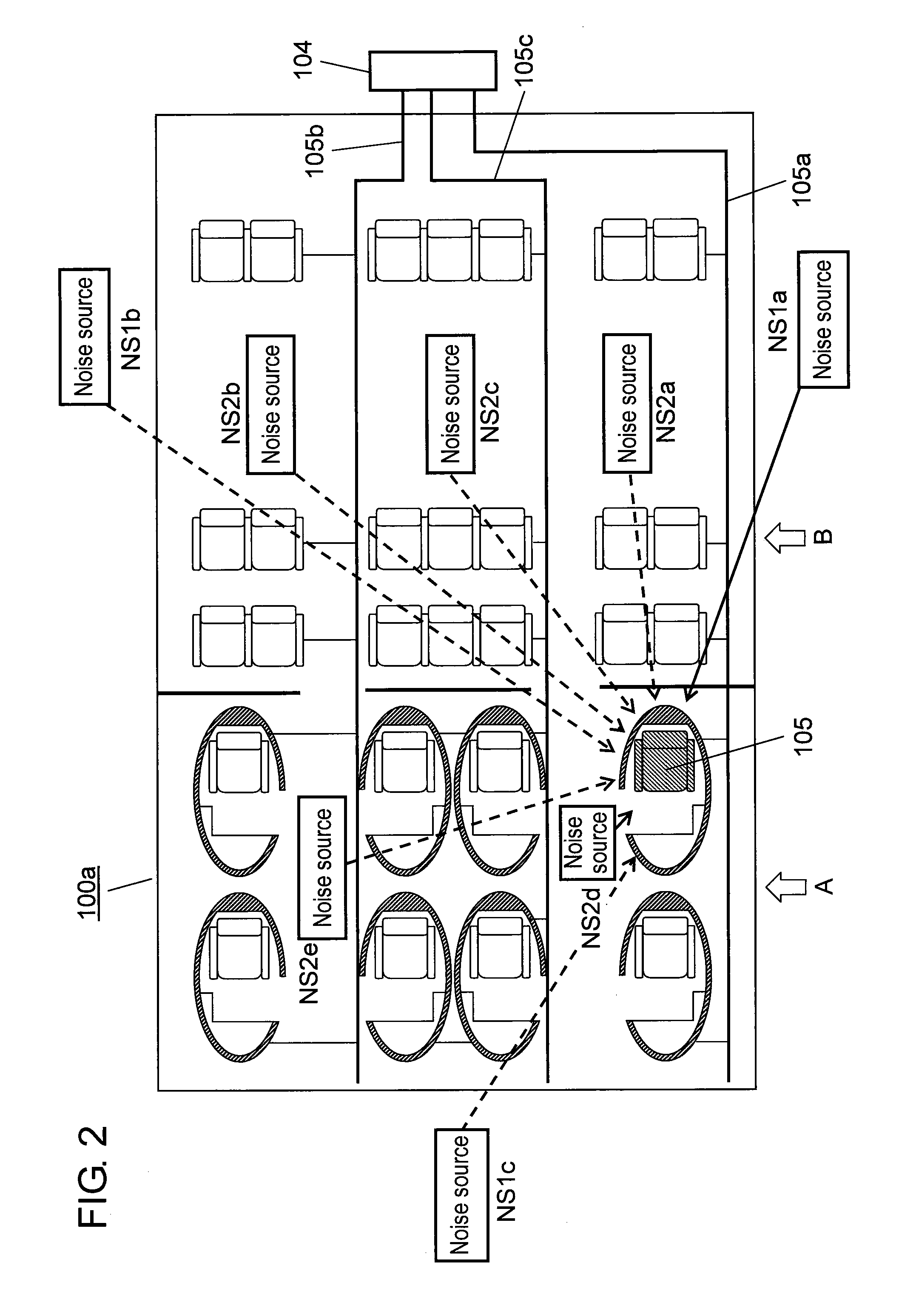
[0062]FIG. 1 is a plan view showing the installation environment of the noise reduction device in the preferred embodiment of the present invention. As shown in FIG. 1, airplane 100 comprises engines 102a, 102b mounted in the right and left wings.

[0063]From the viewpoint of sound environment of the airplane, not only rotating sound but also echoes due to air current are generated from the engine during flying. Therefore, the engine occupies an important position as a noise source. From the viewpoint of passenger services, engines 102a, 102b act upon each part of the airplane body as external noise sources NS1a, NS1b, for example, with respect...


PUM


Abstract

A noise reduction device, including a microphone for detecting noise, a noise controller for reversing the phase of noise detected by the microphone based on information outputted from the microphone, and a speaker for outputting sound based on information outputted from the noise controller, is arranged at a seat surrounded by a shell portion having a cavity, wherein a speaker is disposed in the cavity of the shell portion.

Description

TECHNICAL FIELD[0001]The present invention relates to a noise reduction device in a seat, and particularly, it relates to a noise reduction device to be used in a closed structure such as airplane and train.BACKGROUND ART[0002]In airplanes and trains which generate considerable noise, when information is offered by voice service to the users, problems arise with noise generated at the seats.[0003]In use of an inside space whose boundary is formed by a continuous wall as in an airplane or a train, the place used is a kind of closed structure, and if noise sources exist inside and outside the place used, it will cause a noise environment to be fixed for the users. As a result, although it depends upon the level of noise, the noise exerts physical and mental pressure upon the user, worsening the comfortability of the place used. Particularly, in the case of offering a service to the passengers in the cabin of an airplane, worsening of the comfortability will give serious hindrance to t...

Claims


Application Information

Patent Timeline
IPC IPC(8): A61F11/06B60N2/90
CPCB60R13/0815B64C1/40Y02T50/46G10K2210/1281G10K2210/3221G10K11/178G10K11/17853G10K11/17857G10K11/17861G10K11/17883Y02T50/40
Inventor ASAO, YOSHIFUMIKANO, HIROYUKIHIGASHIDA, MASAAKIMAEDA, TSUYOSHIEZAKI, TOSHIHIRO
Owner PANASONIC INTELLECTUAL PROPERTY MANAGEMENT CO LTD
Why Eureka
Try Eureka