Module Handler Cylindrical Tines Equipped With Retractable Spikes, And Mounting And Drive Arrangements For The Tines

a technology of cylindrical tines and modules, which is applied in the direction of lifting devices, agricultural tools and machines, and agricultural machinery, etc., can solve the problems of lack of durability of the support and drive of the tines

Inactive Publication Date: 2010-05-06
DEERE & CO
View PDF14 Cites 30 Cited by
  • Summary
  • Abstract
  • Description
  • Claims
  • Application Information

AI Technical Summary

Benefits of technology

[0006]An object of the invention is to provide a module handler of the type noted above, but which has powered cylindrical tines which are supported and driven in a reliable and dur

Problems solved by technology

The biggest problem to overcome with removing wrap from a module is getting the wrap out from under the bottom of the module during emptying the cotton contained by the wrapping onto the feeder floor.
Assuming that the wrap will be cut along a line parallel to the axis of the module, a second problem arises, which is to insure that the cut does not occur at the location where the inner tail of the wrapping material is not bonded to the next adjoining wrapping layer.
U.S. patent application Ser. No. 11/928,240, filed on 30 Oct. 2007, discloses such a low cost module handle

Method used


Image

  • Module Handler Cylindrical Tines Equipped With Retractable Spikes, And Mounting And Drive Arrangements For The Tines
  • Module Handler Cylindrical Tines Equipped With Retractable Spikes, And Mounting And Drive Arrangements For The Tines
  • Module Handler Cylindrical Tines Equipped With Retractable Spikes, And Mounting And Drive Arrangements For The Tines

Examples


Embodiment Construction

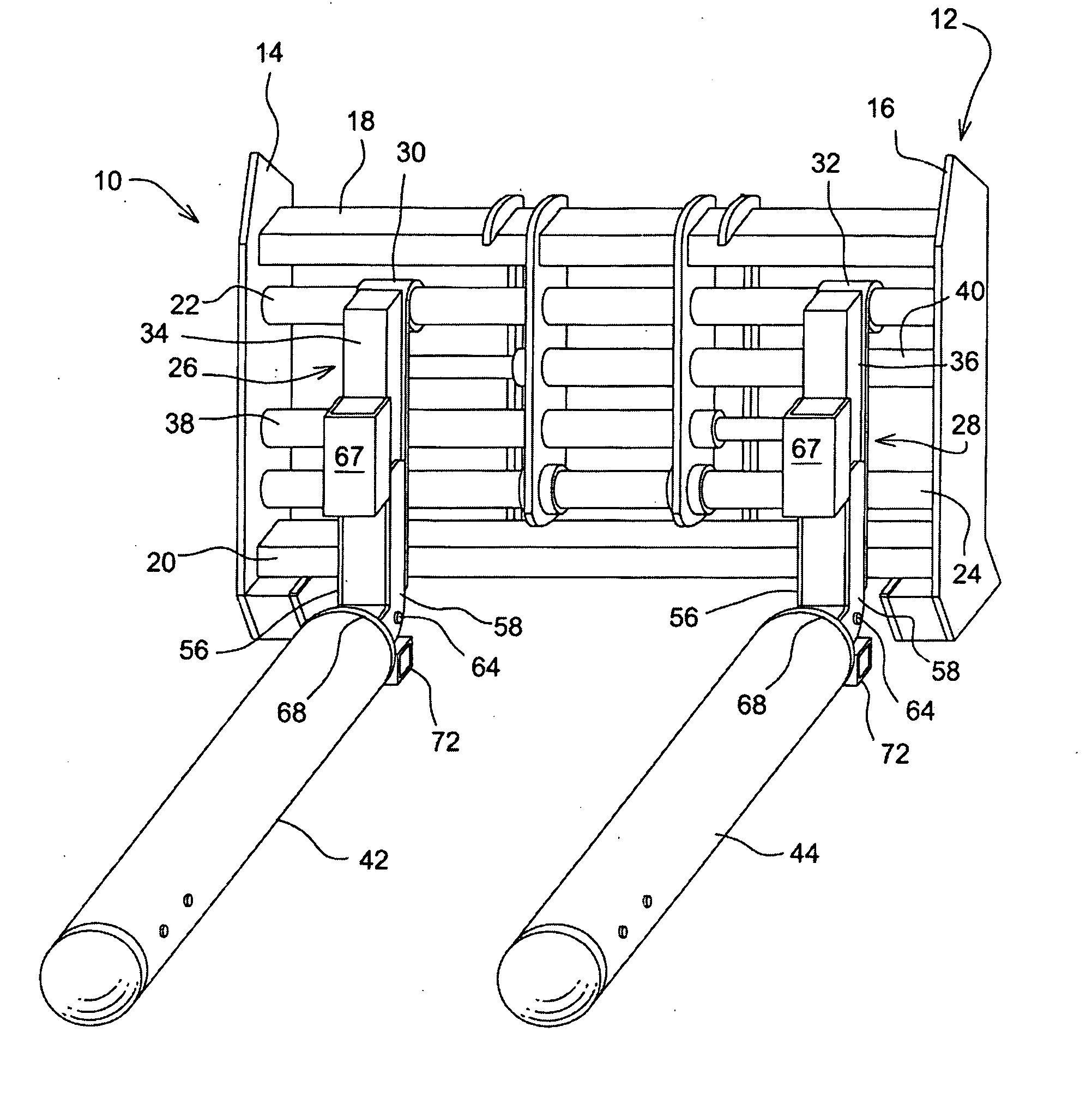
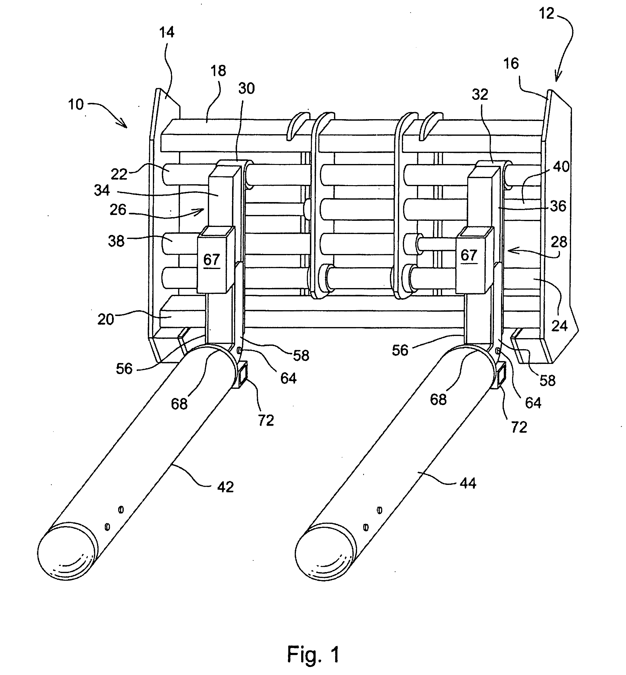
[0023]Referring now to FIG. 1, there is shown a fork implement 10 for being attached to the loader arms of a front end loader, for example. The fork implement 10 includes a support frame 12, including right- and left-hand, upright end members 14 and 16, respectively, joined together by top and bottom cross members 18 and 20, respectively. Also extending between the end members 14 and 16 are upper and lower cylindrical guide members 22 and 24, respectively. Identical, right- and left-hand, conventional L-shaped tines 26 and 28 have respective eyes 30 and 32 formed at upper ends of vertical legs 34 and 36 thereof, the eyes being mounted for sliding along the upper guide member 22. Similar eyes, not shown, are provided below the eyes 30 and 32 and mounted for sliding along the lower guide member 24. Thus, the tines 26 and 28 are mounted for movement towards and away from each other for engaging and releasing cylindrical modules of baled material, such as cotton, for example. Provided f...


PUM

PropertyMeasurementUnit
Diameteraaaaaaaaaa
Distanceaaaaaaaaaa
Circumferenceaaaaaaaaaa

Abstract

A cylindrical cotton module handling device includes an attachment having a pair of selectively spreadable, powered cylindrical tines adapted for supporting and rotating a module. Each powered tine is constructed from a cylindrical tube supported from a conventional L-shaped fork by a tubular sleeve received on, and dimensioned for fitting closely to, the horizontal leg of the conventional fork. The tubular sleeve is held in place by an L-shaped bracket forming a rearward extension of the sleeve and formed for embracing a region of the convention fork at the junction of its vertical and horizontal legs, with a retaining pin extending through vertical side plates of the bracket at a location just to the rear of the junction. An endless roller chain bearing arrangement is secured in encircling relationship to the tubular sleeve and supports the associated cylindrical tine for rotation. A hydraulic motor drive arrangement is mounted to the sleeve and has a shaft borne chain sprocket meshed with a drive chain carried by a rotating drive plates that are keyed to the cylindrical tube. A hydraulically retractable spike assembly is located inside a forward end section of the cylindrical tube and includes a plurality of spikes mounted for being selectively extended outwardly through holes in the tube for engaging a module wrapping during removal of the wrapping from the module.

Description

FIELD OF THE INVENTION [0001]The present invention relates to module handling devices and more particularly relates to module handing attachments equipped with spreadable powered cylindrical tines for supporting and rotating a cylindrical module of cotton or other crop products, for example, covered in a protective covering made of plastic sheet material to a desired position for having the covering slit during removal of the covering.BACKGROUND OF THE INVENTION[0002]A low cost arrangement for removing plastic wrap from cylindrical cotton or stover modules is needed, and is especially needed regarding cotton modules as part of processing the modules on a feeder floor of a cotton gin. While large cotton gins may opt for a more expensive automated arrangement for removing the plastic wrap, a lower cost arrangement is needed for the smaller gins that may require more labor, but less capital costs. The biggest problem to overcome with removing wrap from a module is getting the wrap out ...

Claims


Application Information

Patent Timeline
IPC IPC(8): A01D90/00
CPCA01D87/127A01D2087/128B66F9/143B66F9/18B65B69/0025B66F9/065B66F9/144B29C49/04B29C49/32
Inventor NOONAN, JAMES THOMASRAIL, CLARENCE HAROLD
Owner DEERE & CO
Why Eureka
Try Eureka