

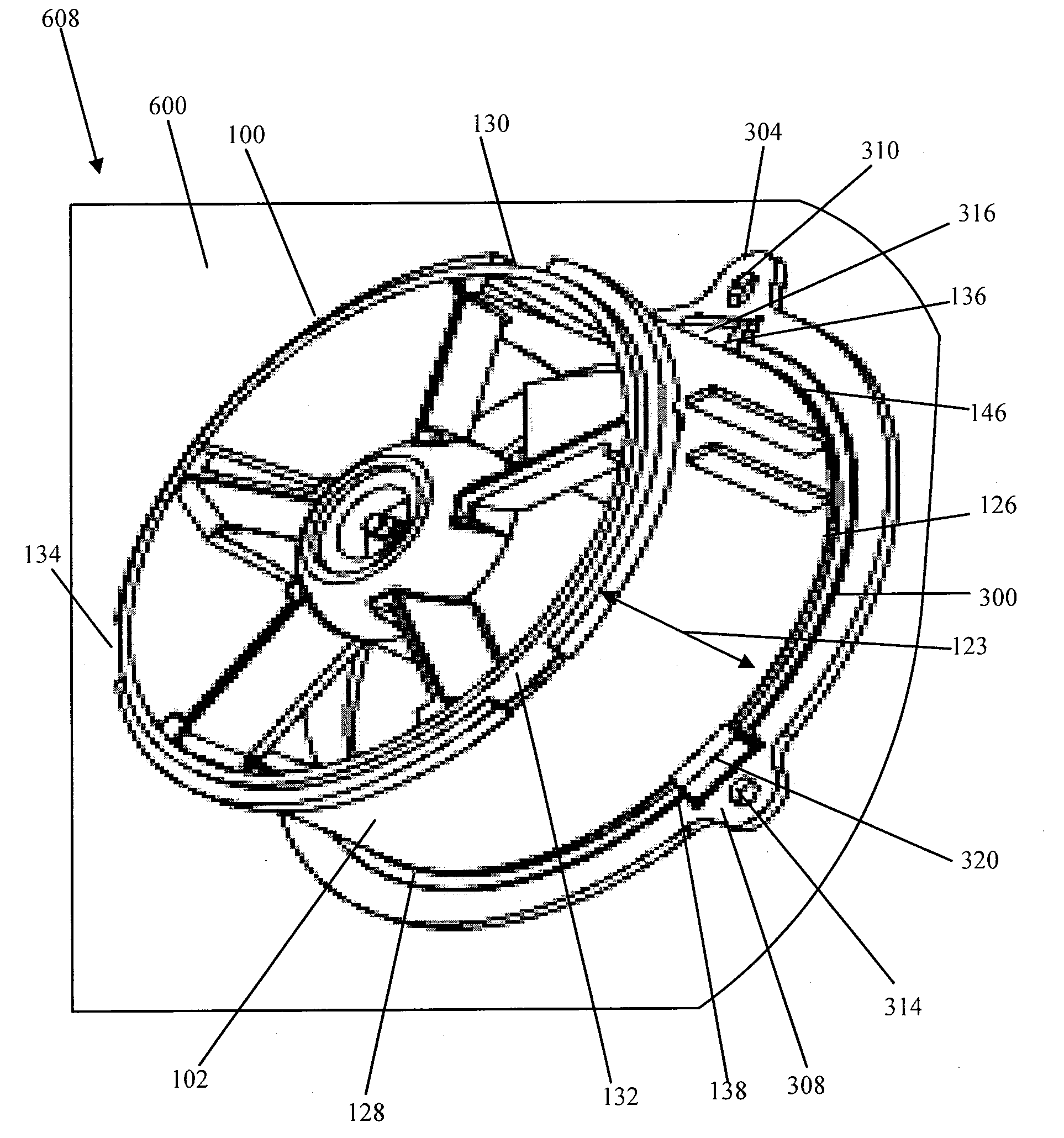
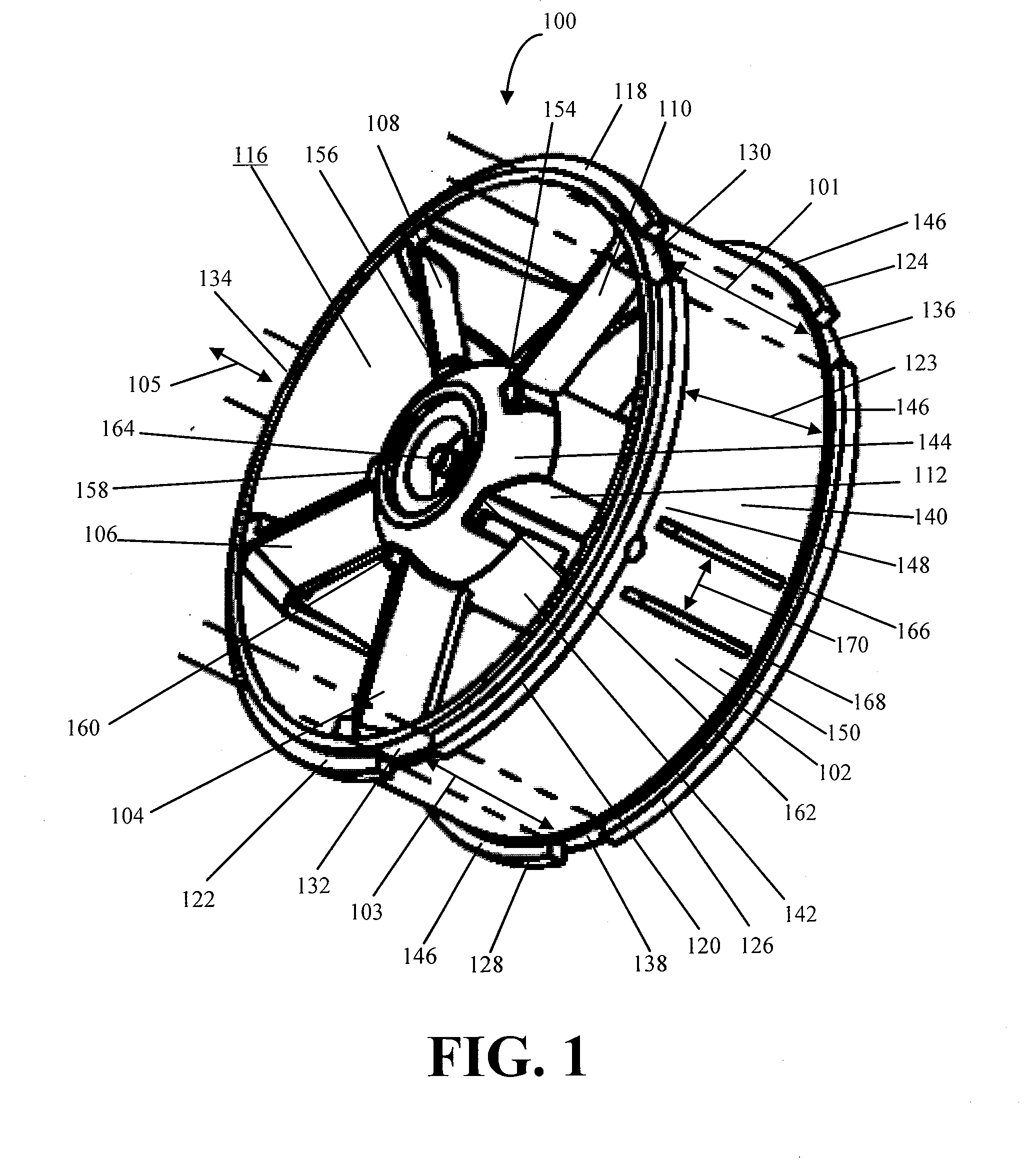
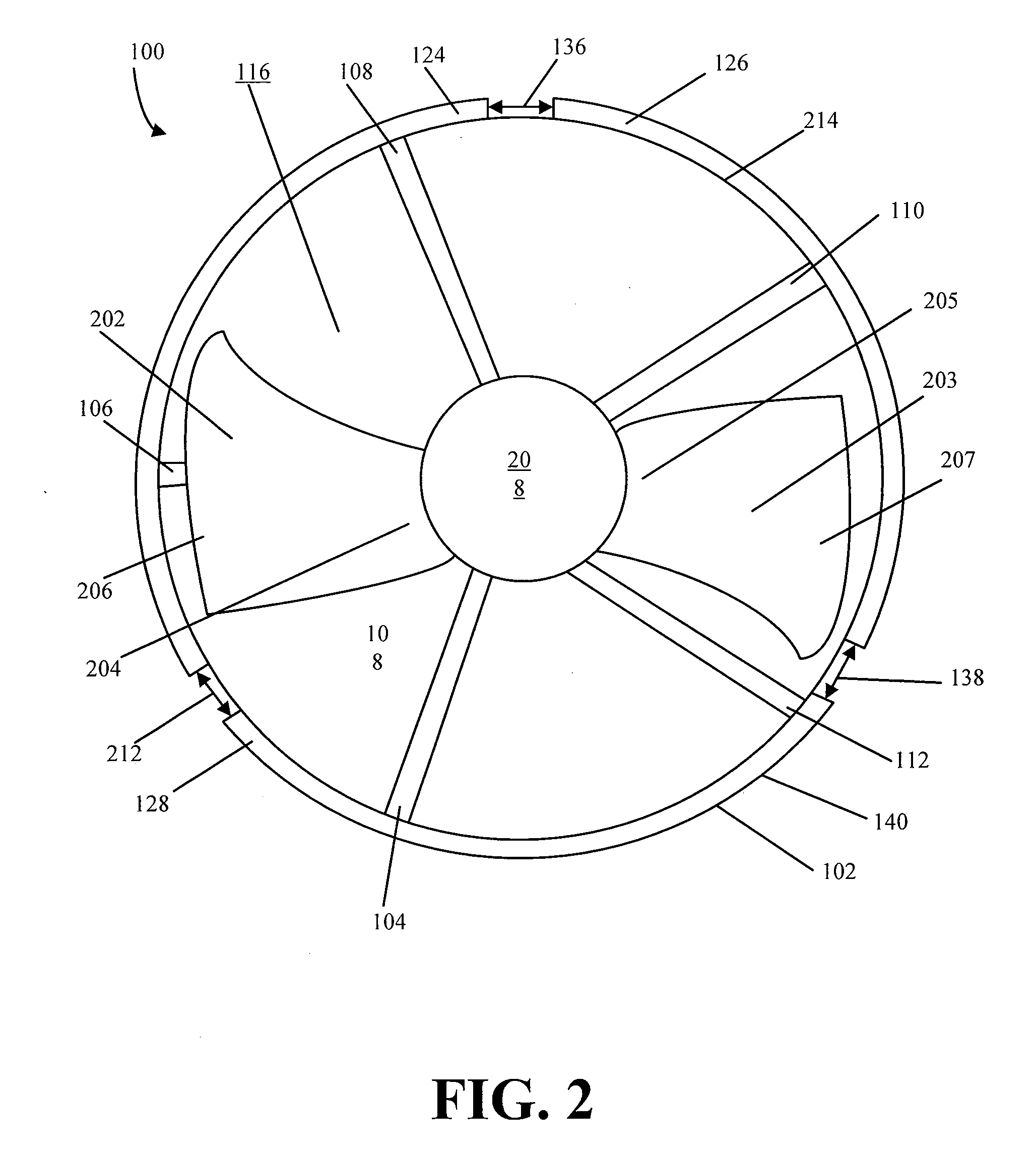
Fan with locking ring
a technology of locking ring and fan, which is applied in the direction of liquid fuel engines, vessel construction, marine propulsion, etc., can solve the problems of complex fans, too expensive for the simple purpose of fan rotation, and many fans are complex in both their structure and their commutation circuitry, so as to achieve simple, efficient and reliable methods.
- Summary
- Abstract
- Description
- Claims
- Application Information
AI Technical Summary
Benefits of technology
Problems solved by technology
Method used
Image

Examples
Embodiment Construction
[0034]Detailed illustrative embodiments of the present invention are disclosed herein. However, techniques, systems, and operating structures in accordance with the present invention may be embodied in a wide variety of forms and modes, some of which may be quite different from those in the disclosed embodiments. Consequently, the specific structural and functional details disclosed herein are merely representative, yet in that regard, they are deemed to afford the best embodiments for the purposes of disclosure and to provide a basis for the claims herein, which define the scope of the present invention. The following presents a detailed description of preferred embodiments (as well as some alternative embodiments) of the present invention.
[0035]A further understanding of the present invention can be obtained by reference to a preferred embodiment. Although the illustrated embodiment is merely exemplary of systems for carrying out the present invention, both the organization and me...
PUM
| Property | Measurement | Unit |
|---|---|---|
| angle alpha | aaaaa | aaaaa |
| angle | aaaaa | aaaaa |
| circumference | aaaaa | aaaaa |
Abstract
Description
Claims
Application Information