Storm shelter structure

a technology for storm shelters and structures, applied in the direction of human health protection, walls, parkings, etc., can solve the problems of damage to any structure, wood frame dwellings are typically the most vulnerable to damage, and downdrafts may include very heavy rain, so as to achieve enhanced protection

Inactive Publication Date: 2010-05-13
OLSEN JEFFREY D
View PDF10 Cites 34 Cited by
  • Summary
  • Abstract
  • Description
  • Claims
  • Application Information

AI Technical Summary

Benefits of technology

[0009]The present invention provides an improved storm shelter construction which provides enhanced protection from penetration by blown debris and from collapse under the weight of building debris. A storm shelter according to the present invention can be supplied as an assembled shelter or as a kit for assembly on the site, such as in a basement, an inside closet, or the like.

Problems solved by technology

Tornadoes and “microbursts” can be damaging to any structure; however, wood frame dwellings are typically the most vulnerable to damage from such storms.
The downdrafts may include very heavy rain.
In addition to strong circumferential horizontal winds, tornadoes create an upward suction, the combination of which can lift roofs and entire houses from their foundations, as well as cause houses to collapse.
Injuries in a home from severe storms, particularly tornadoes, usually involve being struck by flying or falling debris or being crushed by debris from a collapsed house.
However, they are costly, require substantial construction time and, once installed, cannot be relocated.
Because of their size, such prefabricated shelters are fairly expensive to ship and may require specialized equipment for handling and placement in a basement installation.
Previous on-site storm shelter construction was too complicated and time consuming for the average homeowner, but outside the experience of most home builders.
While storm shelter providers could provide skilled installers, the cost of the installation would be substantially increased.
In addition, while properly constructed storm shelters effectively protect their occupants from fierce storms, debris that is hurled by the storm or deposited by collapse of adjacent building structures may block the shelter door.

Method used


Image

  • Storm shelter structure
  • Storm shelter structure
  • Storm shelter structure

Examples


Embodiment Construction

[0022]As required, detailed embodiments of the present invention are disclosed herein; however, it is to be understood that the disclosed embodiments are merely exemplary of the invention, which may be embodied in various forms. Therefore, specific structural and functional details disclosed herein are not to be interpreted as limiting, but merely as a basis for the claims and as a representative basis for teaching one skilled in the art to variously employ the present invention in virtually any appropriately detailed structure.

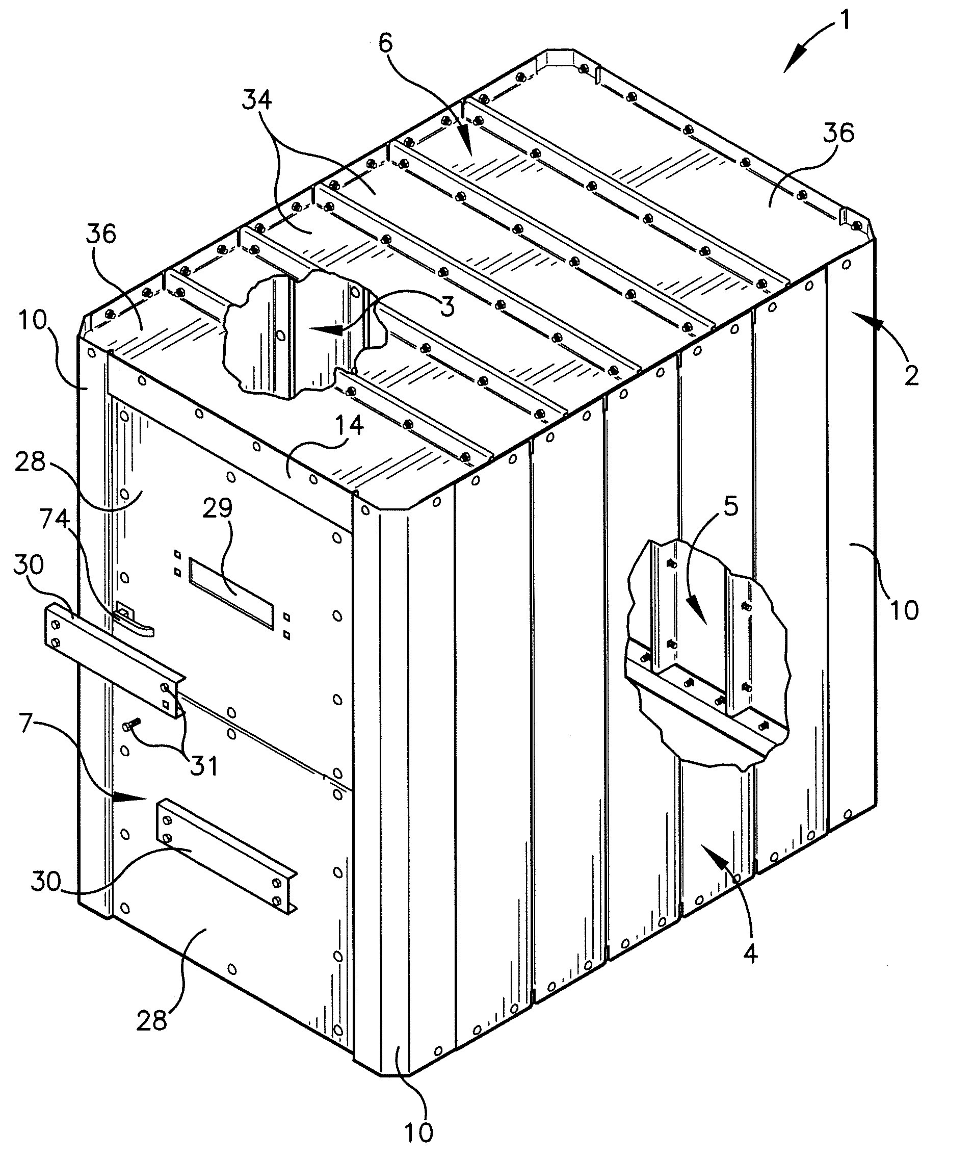
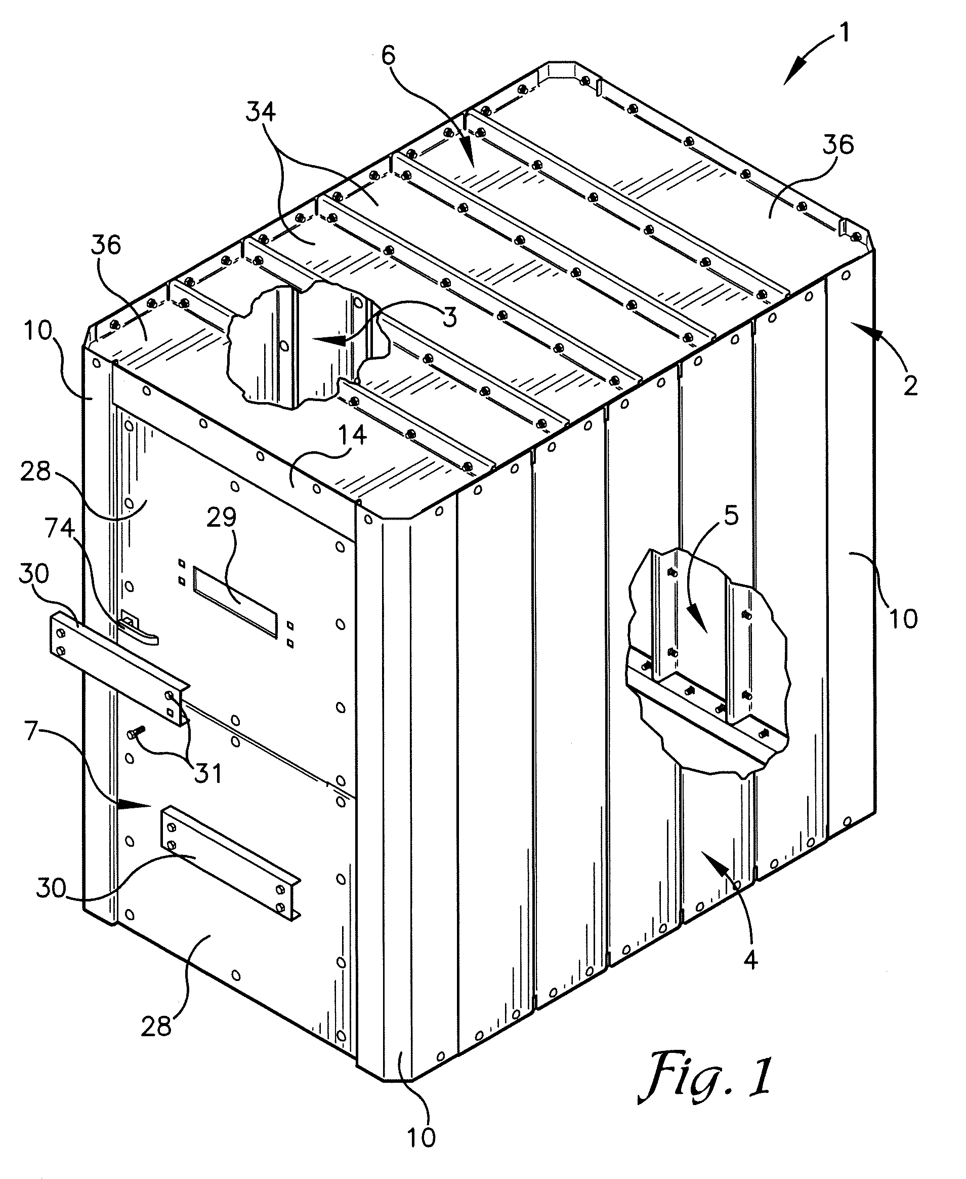
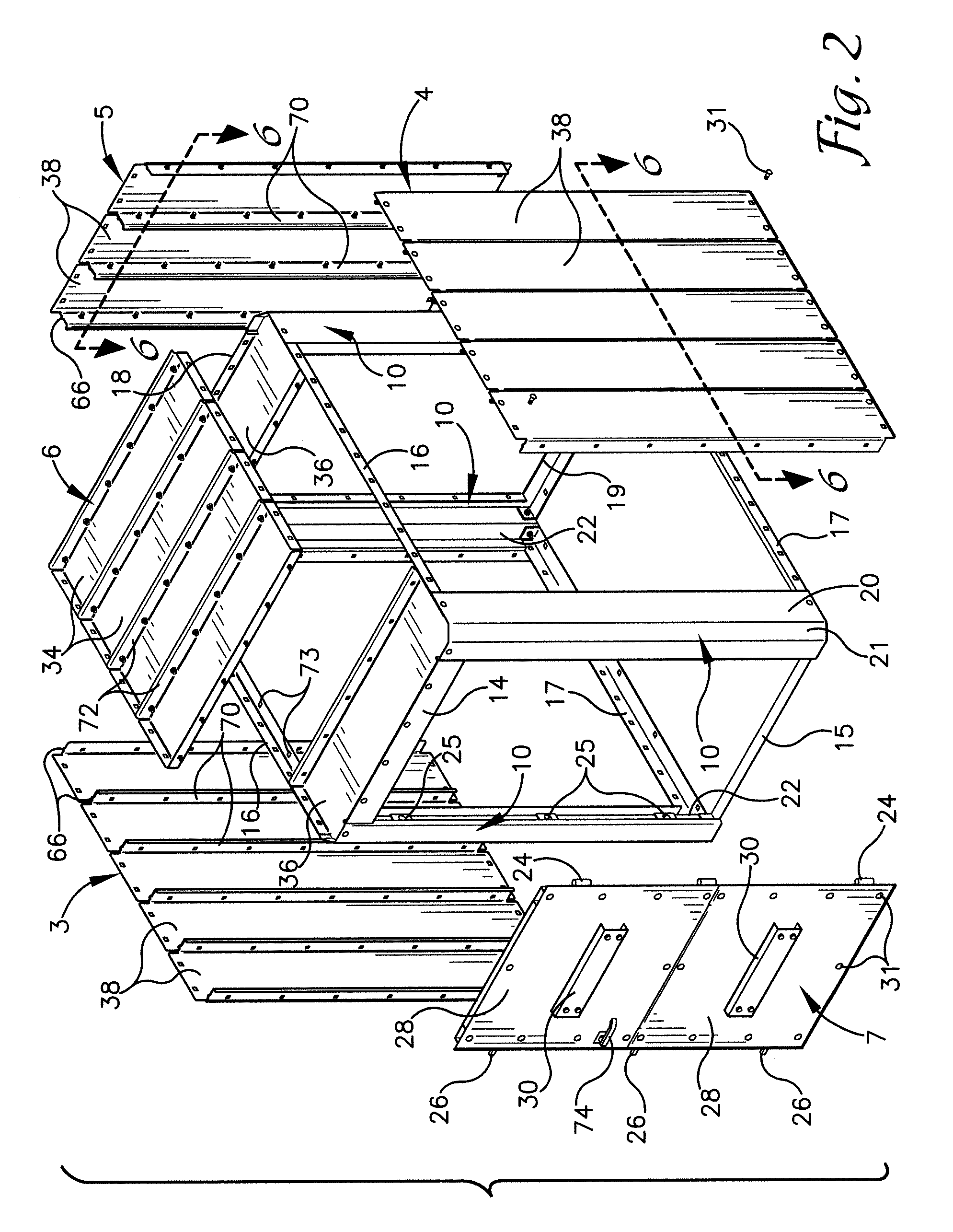
[0023]Referring now to the drawings, the reference numeral 1 generally designates a storm shelter structure according to the present invention. The illustrated structure 1 generally includes a shelter framework 2, left and right side wall panels 3 and 4, a rear wall panel 5 (FIG. 2), a roof panel 6, and a door assembly 7.

[0024]Referring to FIGS. 1 and 2, the framework 2 includes 4 corner vertical assemblies 10 connected by upper and lower front frame members ...


PUM


Abstract

A storm shelter structure provides enhanced protection from penetration by blown debris and from collapse. The shelter has an anchorable framework and door with vent openings having covers removable from the outside to enable emergency access to the door latches. Roof and wall panels are formed of channel members assembled in side-by-side relation. Each channel includes a web with flanges along opposite side edges, one flange including an outwardly extending lip. Channels are fastened side-by-side with a non-lipped flange adjacent a lipped flange. Engagement between the outer edge of a non-lipped flange and a lipped flange increases the stiffness of a rib formed by the joined flanges. Each wall channel flange upper end has a tab aligned with a tab on an adjacent channel for engaging an aperture in the upper frame to facilitate wall assembly and increase gripping between the wall panels and the framework.

Description

CROSS-REFERENCE TO RELATED APPLICATION[0001]This application claims priority under 35 U.S.C. 119(e) and 37 C.F.R. 1.78(a)(4) based upon copending U.S. Provisional Application Ser. No. 61 / 113,890 for STORM SHELTER STRUCTURE filed Nov. 12, 2008, which is incorporated herein by reference.BACKGROUND OF THE INVENTION[0002]The present invention is generally directed to improvements in storm shelters and the like and, more particularly, to construction details of such shelters constructed of formed metal elements.[0003]Although severe storms and tornadoes can occur at virtually anyplace in the world, they are quite common in the midwestern United States. Tornadoes and “microbursts” can be damaging to any structure; however, wood frame dwellings are typically the most vulnerable to damage from such storms. Microbursts create strong downdrafts of air which are diverted to a radially outward horizontal direction when they contact the ground. The downdrafts may include very heavy rain. In addi...

Claims


Application Information

Patent Timeline
Patent Type & Authority Applications(United States)
IPC IPC(8): E04H1/12E04H12/00E06B7/02E04B2/08
CPCE04C2/08E04H9/14Y02A50/00
Inventor OLSEN, JEFFREY D.
Owner OLSEN JEFFREY D
Why Eureka
Try Eureka