Method and apparatus for pollution control of confined spaces

a technology for pollution control and confined spaces, applied in chemical apparatus and processes, separation processes, dispersed particle separation, etc., can solve the problems of 80% of commercial buildings not meeting engineering standards, pollutant is also known to be toxic to humans, and poor indoor air may cost the nation tens of billions of dollars each year in productivity and medical car

Inactive Publication Date: 2010-05-13
AVINA DAVID CHRISTOPHER
View PDF1 Cites 9 Cited by
  • Summary
  • Abstract
  • Description
  • Claims
  • Application Information

AI Technical Summary

Benefits of technology

[0008]In accordance with this instant invention, that utilizes applications and processes known in the art of air pollution control to remove pollutant constituents from a flowing gas stream under pressure through the application of a plurality of alkaline sorbents configured in a manner to absorb pollutants in said gas steam by contact with a full cross sectional area of said sorbent arranged upon a surface of a porous substrate having a plurality of inlets and outlets to allow to said gas to flow through said porous substrate and into the said alkaline sorbent bed comprised of a granular particles contained within a confined space. It is also known in the art that; a directional change to a flowing gas containing entrained particles will cause a large number of the particles to divert from the said flowing gas stream and respond to gravitational force collecting at the lowest point possible. It is also known in the art that contaminated gas flow under pressure will compress a densely packed layer of small diameter alkaline powder (<65 micron) applied to the surface of a porous substrate attached across the inlet and of a flowing gas stream, having a plurality of outlets to provide an efficient means to capture extremely small diameter particles, neutralize acids, absorb volatile organic compounds, capture heavy metals, and particle matter, and kill microorganisms retaining these pollutants within the said packed bed and allowing un-contaminated gas to pass through said bed. The present invention applies these known process in a novel way enclosure of these three processes principles within a first confined space (cartridge) housing having inlets and an outlets, set within a second outer housing containing a propulsion having a prime mover and speed controls, and enabled by a set of pressure switches set between the propulsion system and the fluidized bed plenum to register pressure set points in a way to warn low pressure and high pressure operation stalling operation in the event of set point obtainment.

Problems solved by technology

EPA estimates that poor indoor air may cost the nation tens of billions of dollars each year in lost productivity and medical care.
The National Energy Management Institute (NEMI) reports that approximately 80% of commercial buildings do not comply with engineering standards to provide the best indoor air quality for building occupants.
Ozone: O3 is as a powerful oxidant found in nature and generated by printing process, this pollutant is also known to be toxic to humans in small concentrations above 10 ppm.
Ozone is a health hazard that can cause eye and mucous membrane irritation and chronic respiratory disease.
Current indoor environment pollution control technology is unable to provide one system to filter particulate matter, absorb VOC's, neutralize acids, capture heavy metals, and provide a 99.99% kill rates of all known microorganisms.
In addition to insufficient control capability the present technologies in the retail and commercial market have a inherent health risk over seen by current studies which involves user handing of dirty filters during replacement, as filters are removed exposure is many times higher than normal breathing air in a contaminated room.
Other aspects of prior art technology have been known to be harmful and have been reported in EPA studies and many other government agencies.

Method used


Image

  • Method and apparatus for pollution control of confined spaces
  • Method and apparatus for pollution control of confined spaces
  • Method and apparatus for pollution control of confined spaces

Examples


Embodiment Construction

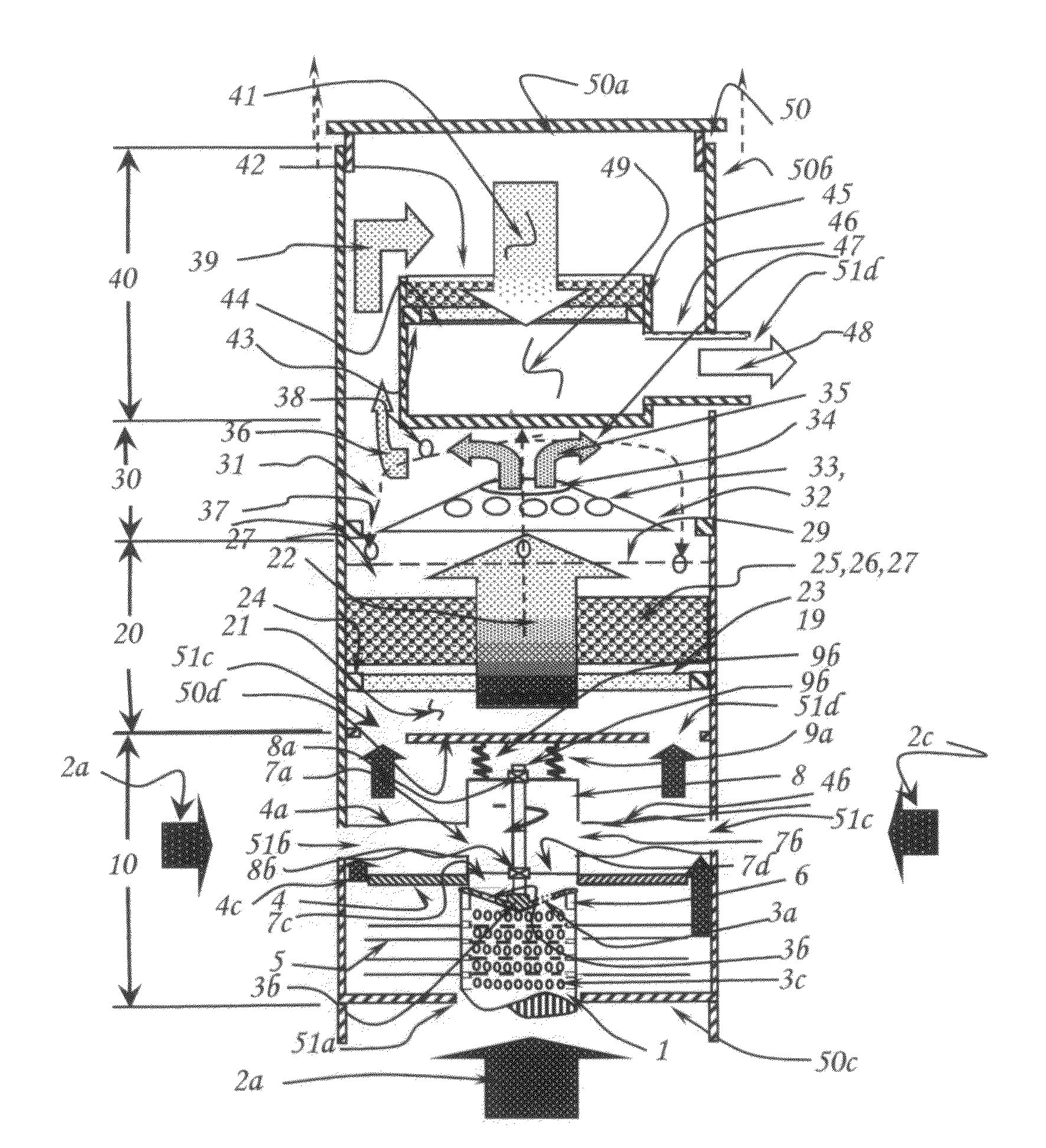
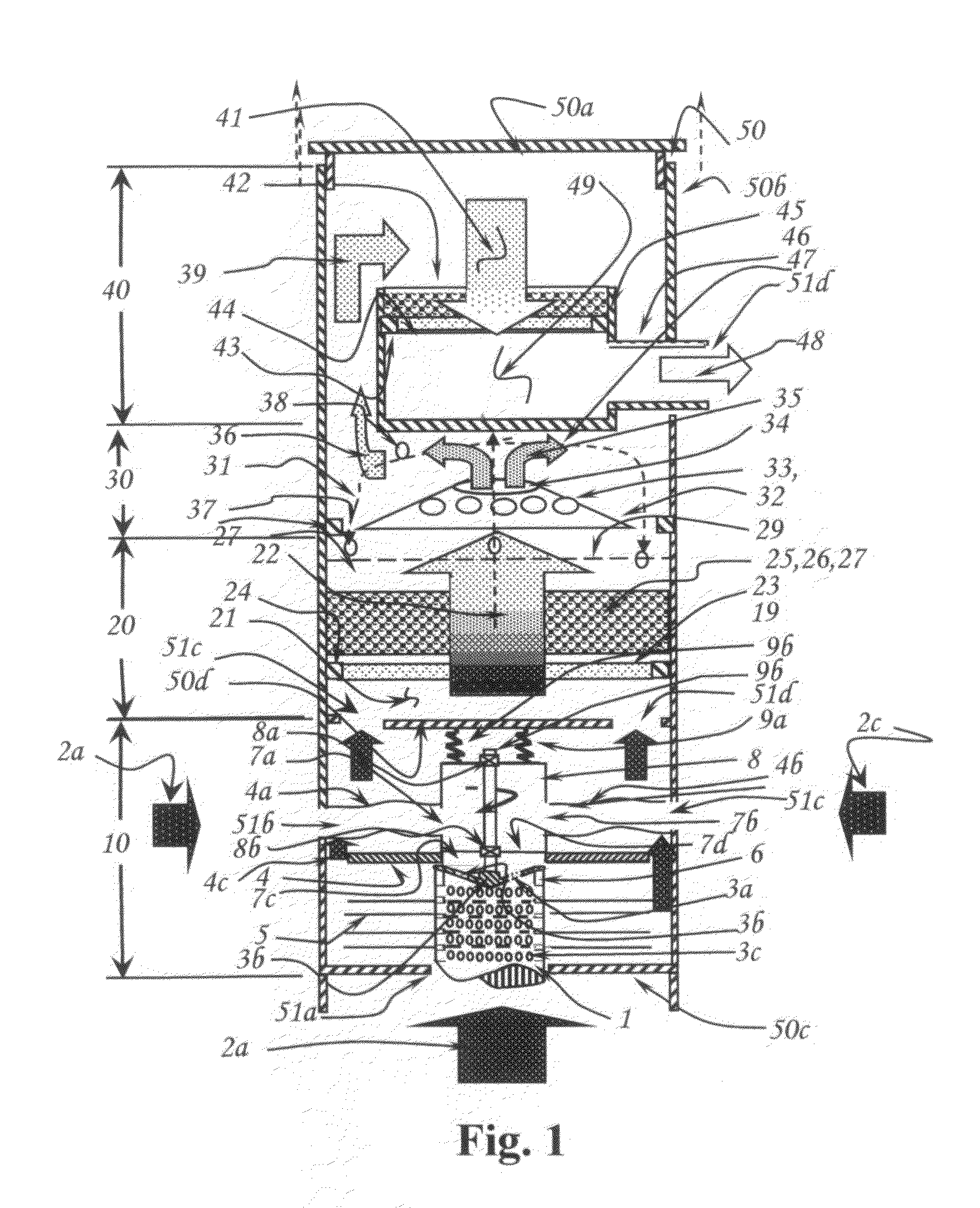
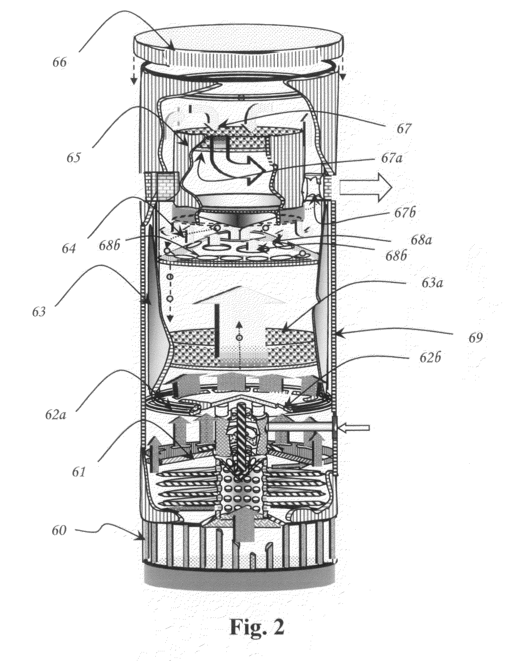
[0016]The present invention will be described with reference to the accompanying drawings which assist in illustrating the pertinent features thereof. The apparatus illustrated in FIG. 1, is a basic flow diagram of this instant air filtration invention, supplemented by U.S. patent application Ser. No. 10 / 867,943 filed on Jun. 14, 2004 entitled “Method And Apparatus For Combined Cycle Fluid Propulsion”, dealing with the boundary layer propulsion apparatus method of operation, supplemented in present art to stated the mode of operation as applied to the present air filtration apparatus currently under presentation in this invention.

[0017]In the current invention an occupied confined space (not shown) having contaminated air and represented in the current embodiment by confined space inlet air containing volatile organic compounds, heavy metals, acids, particulate matter, and living microorganisms, in said supply (2a, 2b, 2c), is induced into an enclosure (50), having an inner and oute...


PUM

PropertyMeasurementUnit
particle diametersaaaaaaaaaa
temperaturesaaaaaaaaaa

Abstract

A method of improve the removal of particulate matter, heavy metals, neutralizing acid, and kill microorganism pollutants, known to be in contaminated air volumes of occupied confined spaces, when exposed in close contact under pressure to a mixture of alkaline sorbent materials, having a known synergism between said pollutants using a self propelled fluidized bed reactor and packed bed filter apparatus system to optimize the contact collection efficiency of submicron particles and organic compounds.

Description

CROSS REFERENCE TO RELATED PATENTS AND APPLICATIONS[0001]This invention is This invention is a continuation-in-part of U.S. patent application Ser. No. 11 / 001,811 and this application and also based on prior art U.S. Pat. No. 6,451,091 B1, entitled “Apparatus and Method for Emissions Control Through Continuous Filtration System” and U.S. patent application Ser. No. 10 / 867,943 filed on Jun. 14, 2004 entitled “Method And Apparatus For Combined Cycle Fluid Propulsion”.BACKGROUND OF INVENTION[0002]This instant invention relates to a method and apparatus useful in the removal of harmful pollutants known to be found in occupied confined spaces to the improvement of indoor air quality. A 1989 EPA Report to Congress concluded that improved indoor air quality can result in higher productivity and fewer lost workdays. EPA estimates that poor indoor air may cost the nation tens of billions of dollars each year in lost productivity and medical care. The National Energy Management Institute (NEM...

Claims


Application Information

Patent Timeline
Patent Type & Authority Applications(United States)
IPC IPC(8): B01D53/02B01D53/12B01D53/04
CPCB01D53/0407B01D53/12B01D53/52B01D53/58B01D53/64B01D53/72B01D53/83B01D2251/304B01D2251/606B01D2253/102B01D2253/304B01D2257/304B01D2257/406B01D2257/602B01D2257/7027B01D2257/708B01D2257/91
Inventor AVINA, DAVID CHRISTOPHER
Owner AVINA DAVID CHRISTOPHER
Why Eureka
Try Eureka