Case having signal transmission line

a signal transmission line and case technology, applied in the field of cases, can solve the problems of difficult wiring implementation within the device, high manufacturing cost, etc., and achieve the effect of lowering the overall cost and reducing the manufacturing cost of the external ground layer of the signal transmission lin

Inactive Publication Date: 2010-05-13
SMART APPROACH
View PDF2 Cites 2 Cited by
  • Summary
  • Abstract
  • Description
  • Claims
  • Application Information

AI Technical Summary

Benefits of technology

[0010]The case having a signal transmission line further includes an insulating layer and a conductive layer. The insulating layer is located between the groove and the core, so as to insulate the core from the case body. The insulating layer surely wraps the core and insulates the core from the exterior. The conductive layer is located between the groove and the insulating layer, so as to protect a signal transmitted via the core from being interfered by external electromagnetic waves.
[0011]In the case having a signal transmission line according to the present invention, at least one groove is disposed on the case body and a signal transmission line having a core is disposed within the groove. Meanwhile, the core is insulated from the exterior by means of being wrapped by an insulating layer, or disposing the insulating layer between the groove and the core, and is used to transmit a signal. By employing a case body made of a metal or a conductive layer disposed within the groove of the case body to serve as a ground layer of the signal transmission line, the influences on the signal transmission of the inner core caused by the external electromagnetic waves can be avoided. On one hand, the case having a signal transmission line can overcome the wiring difficulty of the signal transmission line; on the other hand, the manufacturing cost of the external ground layer of the signal transmission line can be reduced, thereby lowering the overall cost.

Problems solved by technology

However, the antenna disposed at an exterior of the device not only influences the size and appearance of the product, but also has defects of being easily crashed by an external force, easily flexed and broken up, so the built-in antenna has already become a tendency of a mainstream.
However, since the current device tends to be much lighter and thinner, when a signal transmission line is disposed in a device for electrically connecting a built-in antenna device to a microprocessor, it is rather difficult to implement the wiring within the device due to the volume of the signal transmission line.
However, the manufacturing cost is generally quite high due to a high cost of the signal transmission line.

Method used


Image

  • Case having signal transmission line
  • Case having signal transmission line
  • Case having signal transmission line

Examples


first embodiment

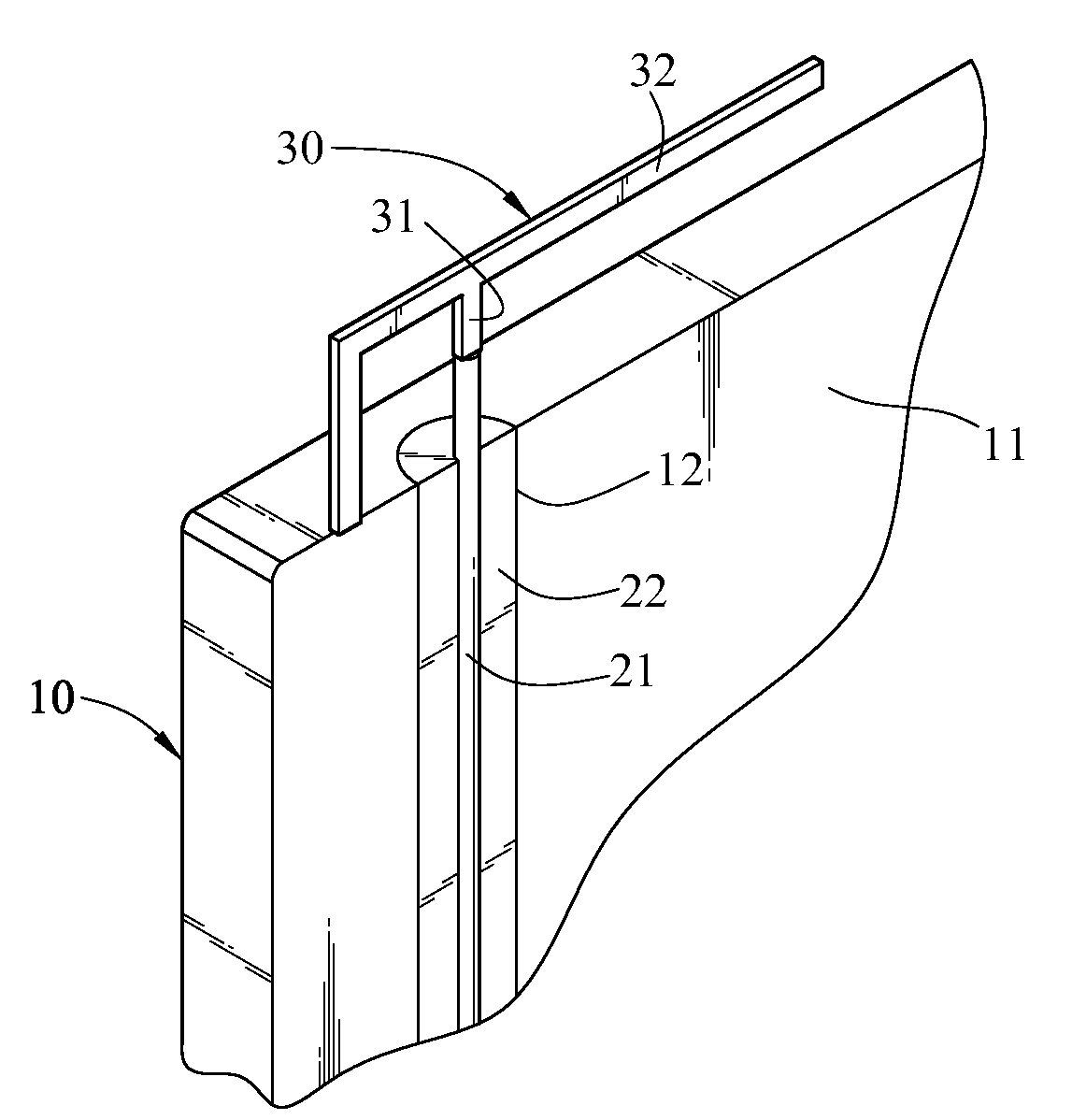
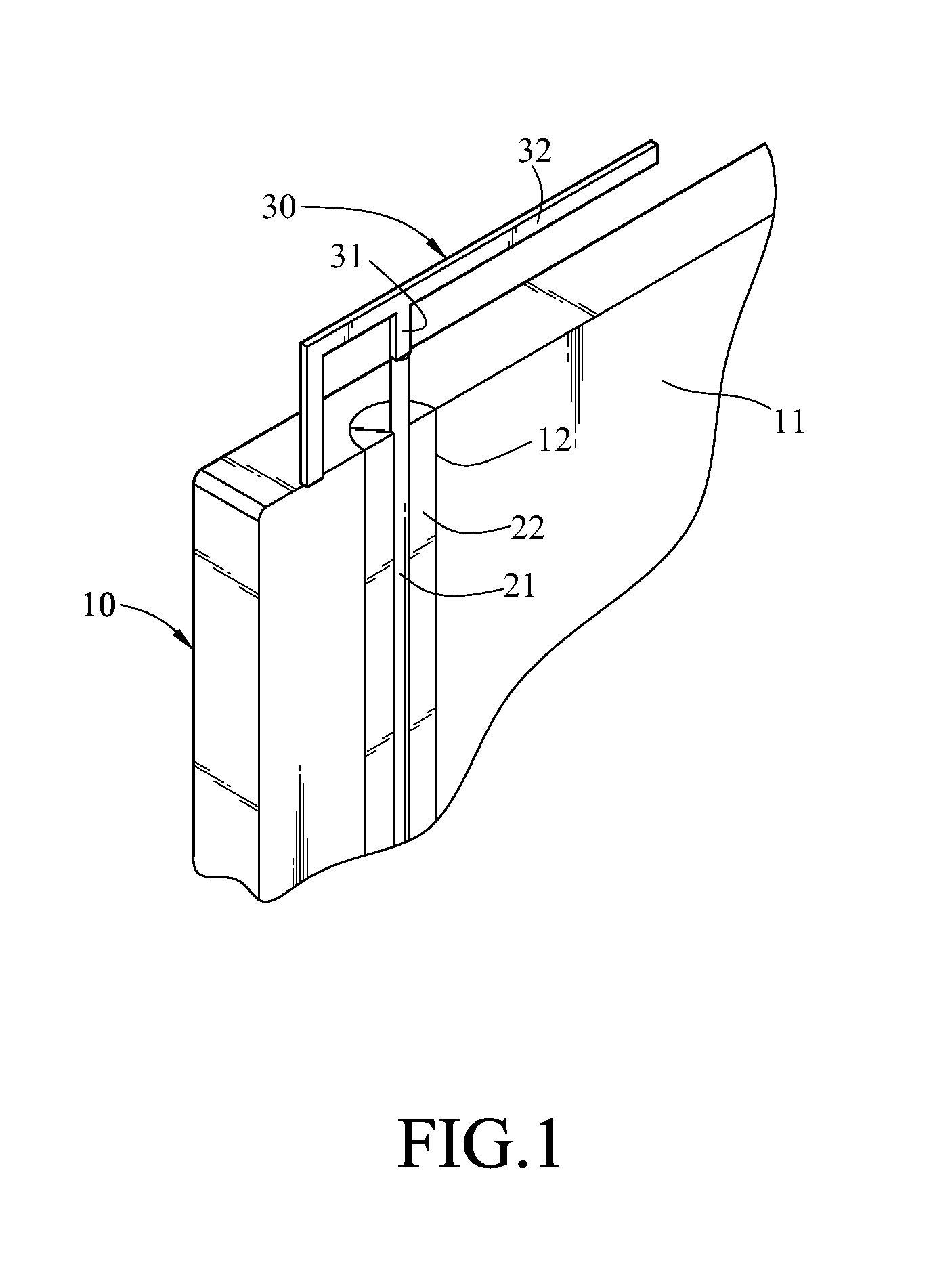
[0016]FIG. 1 is a schematic view of the present invention. In this embodiment, a case having a signal transmission line includes a case body 10 and a signal transmission line, and an antenna 30.

[0017]The case body 10 has a surface 11 with a groove 12 disposed thereon.

[0018]The signal transmission line is positioned within the groove 12, and includes a core 21. The core 21 is a conductor used for transmitting a signal.

[0019]The case having a signal transmission line further includes an insulating layer 22. The insulating layer 22 is located between the groove 12 and the core 21, so as to insulate the core 21 from the case body 10. In this embodiment, the insulating layer 22 is located on the surface of the groove 12, and isolates the core 21 from the case body 10 made of a metal.

[0020]The antenna 30 has a signal feed-in portion 31 and a radiation portion 32. The signal feed-in portion 31 is connected to the core 21. The core 21 is used to feed a signal into the radiation portion 32 v...

second embodiment

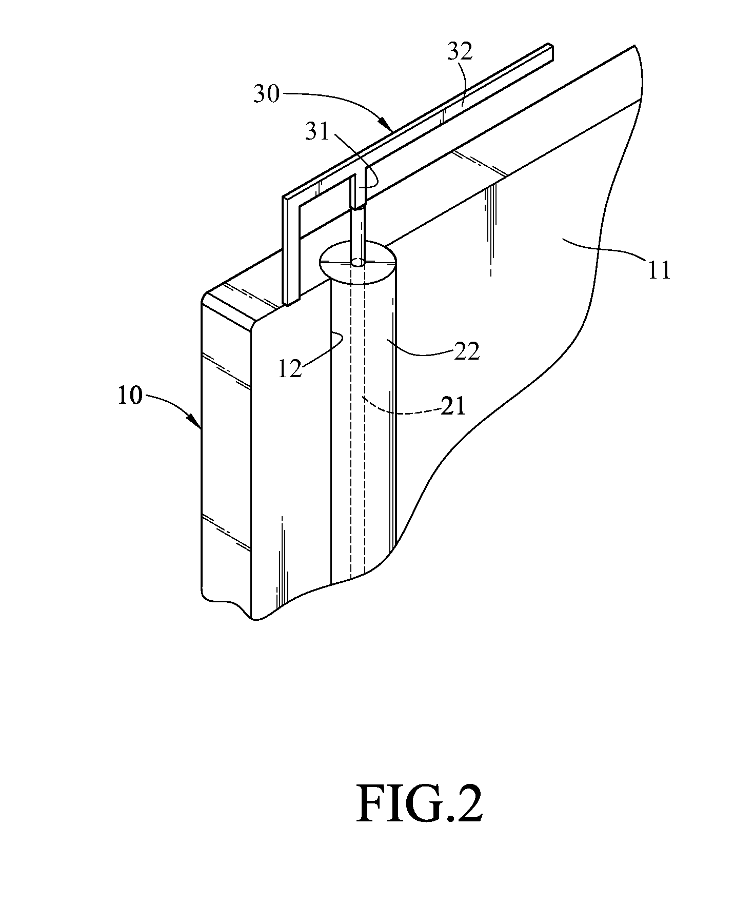
[0026]FIG. 2 is a schematic view of the present invention. The structure design in this embodiment is substantially similar to that in the above embodiment, but differs in that, the insulating layer 22 wraps the core 21 and insulates the core 21 from the exterior. In this way, the core is prevented from contacting other elements on the other side of the case body 10 to result in the loss of signal.

[0027]FIG. 3 is a schematic view of a third embodiment of the present invention. The structure design in this embodiment is substantially similar to that in the second embodiment, but differs in that the case body 10 in this embodiment may be made of other nonmetallic materials such as plastic and carbon fiber.

[0028]However, since the case body 10 may be made of a nonmetallic material, or a metal material with a poor conductivity, it cannot be used as a ground layer to ground the signal, and cannot protect the signal transmitted via the core from being interfered by external electromagneti...


PUM


Abstract

A case having a signal transmission line includes a case body and a signal transmission line. The case body has a surface with at least one groove disposed thereon. The signal transmission line is positioned within the groove, and has a core for transmitting a signal. The case having a signal transmission line further includes an insulating layer. The insulating layer is located between the groove and the core, so as to insulate the core from the case body. By employing the case body or a conductive layer coated in the groove to serve as a metal ground layer, the external electromagnetic wave interference can be avoided when transmitting a signal via the signal transmission line, and the manufacturing cost of the signal transmission line can be effectively reduced as well.

Description

BACKGROUND OF THE INVENTION[0001]1. Field of the Invention[0002]The present invention relates to a case, and more particularly to a case having a signal transmission line.[0003]2. Related Art[0004]Wireless communication technology utilizes electromagnetic waves to transmit signals, so that it communicates with a remote device without connecting to a wire in usage. Therefore, the wireless communication technology is quite convenient while a user moves all around. Accordingly, more and more products using wireless communication technology have been proposed currently such as a mobile phone, and a laptop computer. However, since these products utilize electromagnetic waves to transmit signals, an antenna used to receive and transmit electromagnetic wave signals becomes an indispensable element. Nowadays, the antenna is mainly classified into an antenna disposed at an exterior of the device, and an antenna built in the device. However, the antenna disposed at an exterior of the device n...

Claims


Application Information

Patent Timeline
Patent Type & Authority Applications(United States)
IPC IPC(8): H05K5/00
CPCH01Q1/2258H01Q1/2266H01Q9/0421H04B1/3833
Inventor LIN, HSIN-LUNG
Owner SMART APPROACH
Why Eureka
Try Eureka