Landing gear

a landing gear and gear technology, applied in the field of aircraft, can solve the problems of significant load in such components of landing gear, and the landing gear is subject to considerable loads, and achieve the effect of improving the trimming and positioning arrangement of the bogi

Inactive Publication Date: 2010-05-13
AIRBUS OPERATIONS LTD
View PDF14 Cites 31 Cited by
  • Summary
  • Abstract
  • Description
  • Claims
  • Application Information

AI Technical Summary

Benefits of technology

[0006]It is an aim of the present invention to provide an aircraft landing gear with an improved bogie trimming and positioning arrangement.

Problems solved by technology

During use, and more particularly during take-off and landing, an aircraft landing gear is subjected to considerable loads

Method used


Image

  • Landing gear
  • Landing gear
  • Landing gear

Examples


first embodiment

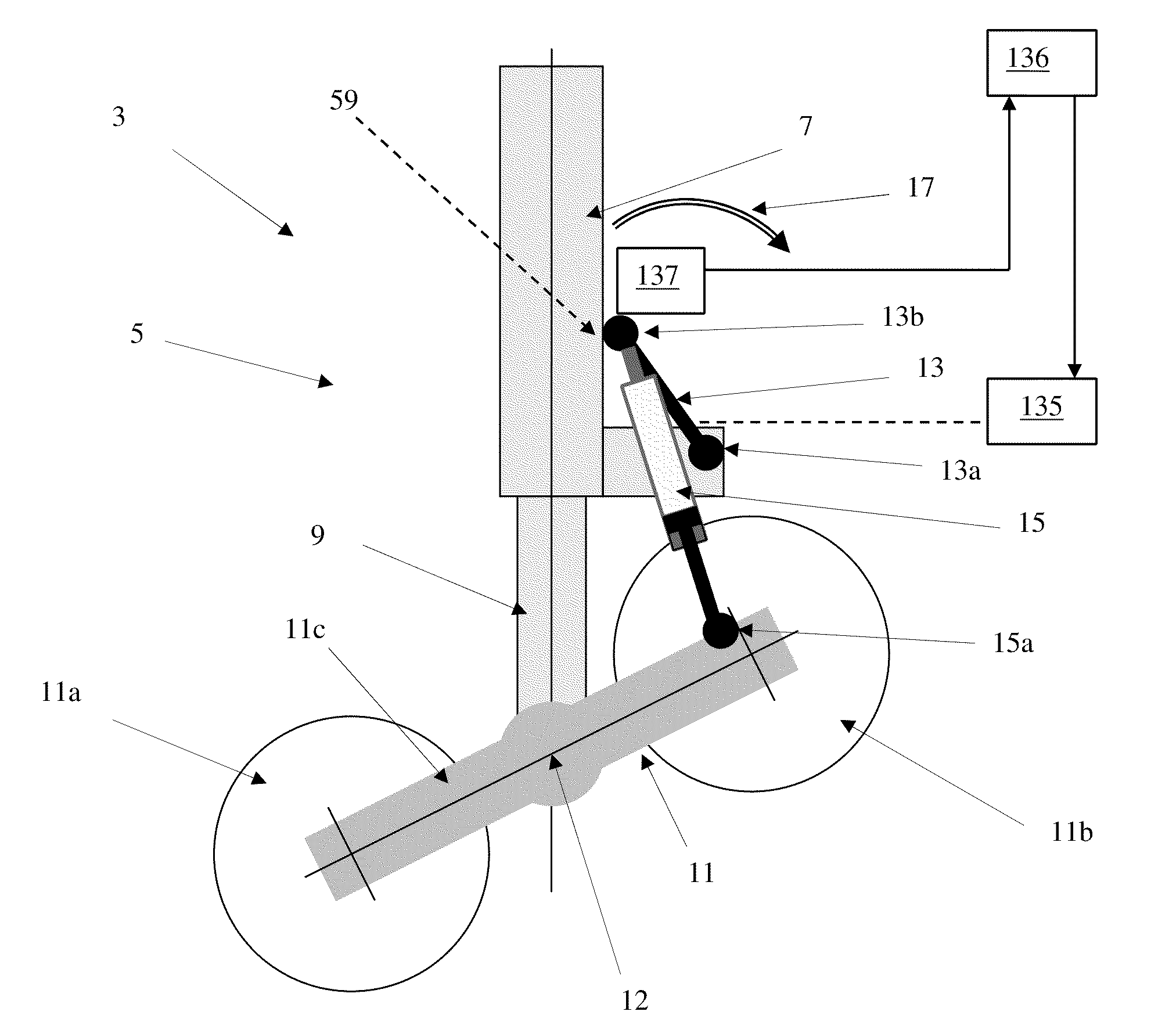
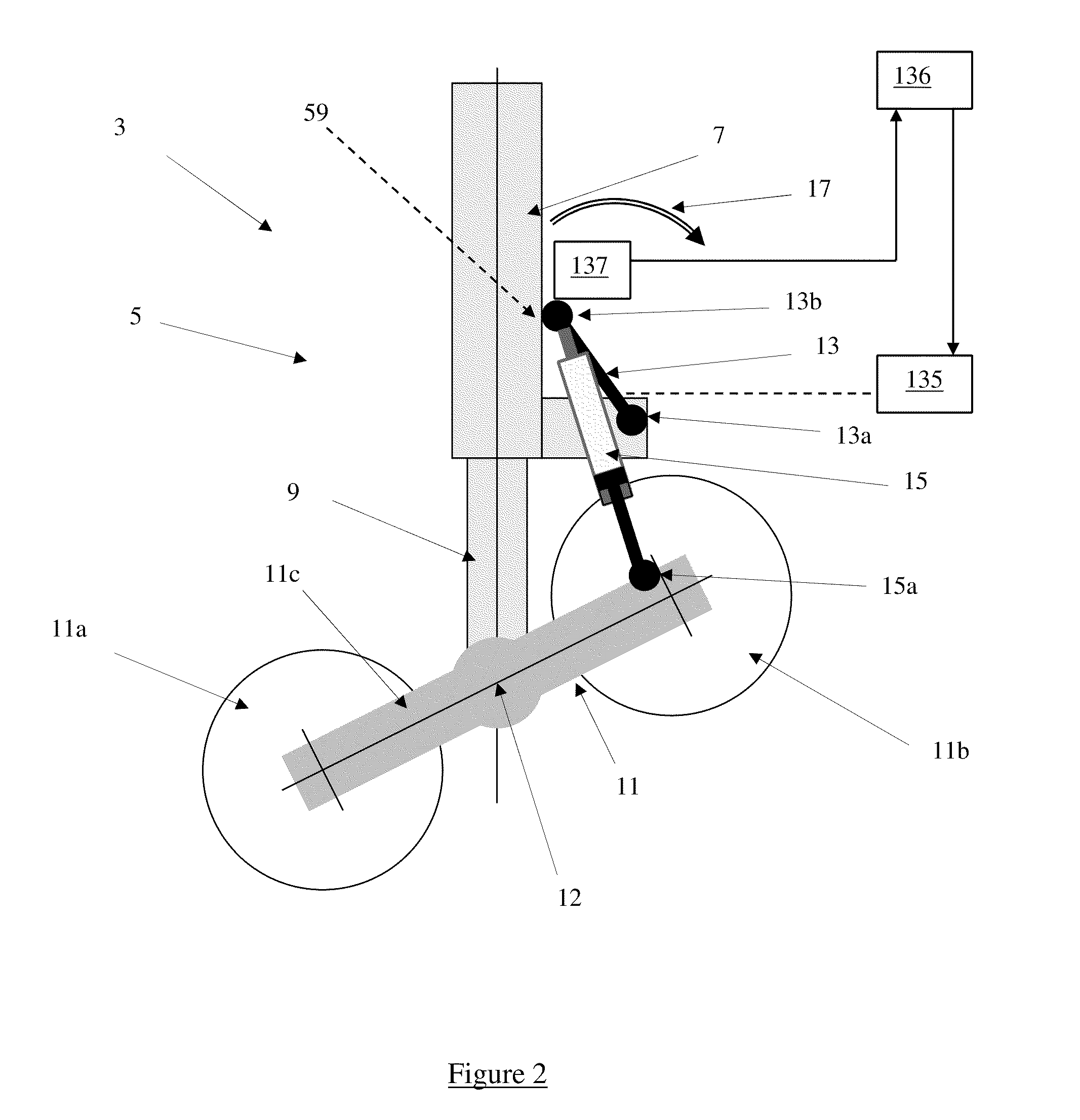
[0031]FIG. 3 shows the arm 13 is in a second position and the bogie 11 in a stowable position. In the invention, the stowable position is such that the bogie 11 is perpendicular to the leg 5. The bogie 11 is positioned in the stowable position shortly before the landing gear 3 is retracted into the aircraft 1. Movement of the bogie 11 between the trimmed deployed position and the stowable position will now be described with reference to both FIGS. 2 and 3.

[0032]With the landing gear in the position shown in FIG. 2, a control unit (not shown) sends a signal to a rotary positioning actuator (not shown) which in turn causes rotation of the arm 13 in a direction shown by the arrow 17 in FIG. 2. The rotary actuator is located in a bearing on the leg, and is in the form of an electro-mechanical worm-gear arrangement. The rotary actuator has a duplicated gearbox and motor as a safety precaution and has a failure rate in the order of 5.0×10⁻⁸ per flight hour.

[0033]The rotary positioning act...

second embodiment

[0037]According to the invention (not shown) the rotary actuator is provided with a fail-safe device. When the actuator is subjected to excessive torsion and the bogie is in the stowable position, a fusible structural element in the device is arranged to shear, allowing the arm to rotate away from the second position. If, for example, the aircraft is forced to land with the bogie in the stowable position, the arm will therefore rotate to allow the bogie to freely achieve a stable alignment and a significant portion of the loads generated during landing may be reacted through the arm 13 and link 15 and the bearing at 13a.

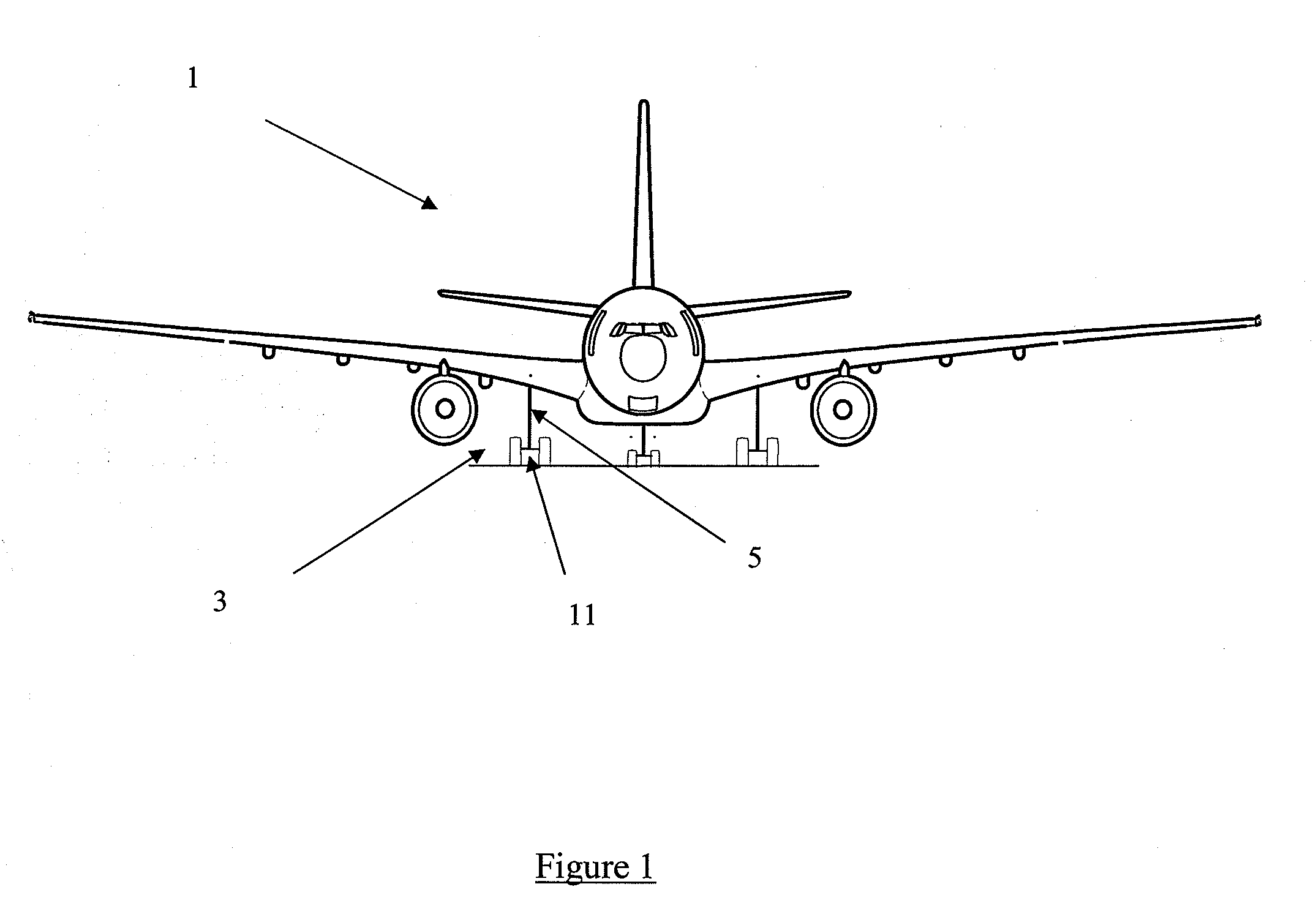
[0038]The invention is of greater application to larger aircraft. The aircraft is preferably of a size equivalent to an aircraft designed to carry more than 50 passengers, and more preferably more than 100 passengers.


PUM


Abstract

In an aircraft having an aircraft landing gear, the aircraft landing gear includes an arm, a leg and a bogie at the lower end of the leg. The bogie is moveable in a direction along the length of the leg and pivotable between a trimmed deployed position and a stowable position. The arm is mounted on the landing gear and is rotatable between a first position in which the bogie is positioned in the trimmed deployed position, and a second position in which the bogie is positioned in the stowable position. Movement of the arm can be effected by a positioning rotary actuator, which is not located in the primary or secondary load paths.

Description

RELATED APPLICATIONS[0001]The present application is based on, and claims priority from, British Application Number 0515359.8, filed Jul. 26, 2005, the disclosure of which is hereby incorporated by reference herein in its entirety.TECHNICAL FIELD[0002]The present invention relates to aircraft. In particular the invention relates to an aircraft including an aircraft landing gear having an apparatus for alignment of a landing gear bogie.BACKGROUND OF THE INVENTION[0003]Many aircraft include a landing gear assembly comprising a pivotable bogie such that when the aircraft is on the ground, the bogie is generally aligned with the ground, whereas just prior to landing, and immediately following take-off, the bogie can be trimmed at an angle to the ground. Trimming the bogie in such a way provides a number of advantages as will be understood by the person skilled in the art.[0004]It is advantageous to be able to stow a landing gear assembly during flight, and more particularly to stow the ...

Claims


Application Information

Patent Timeline
IPC IPC(8): B64C25/10B64C25/18B64C25/34
CPCB64C25/34
Inventor GRIFFIN, JOHN WILLIAM
Owner AIRBUS OPERATIONS LTD
Why Eureka
Try Eureka